How to test the power consumption of "System ON IDLE with GRTC (XOSC) and 256 KB RAM"

HI ALL,

   I used a system off demo and added the following content.

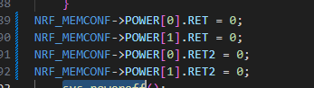
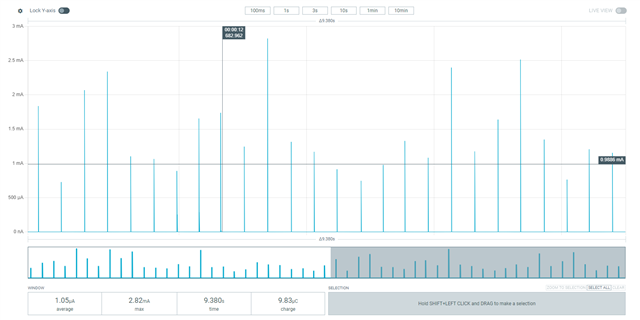
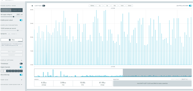
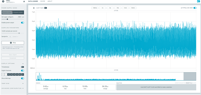
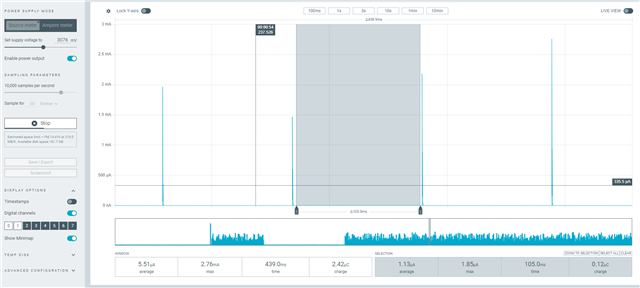
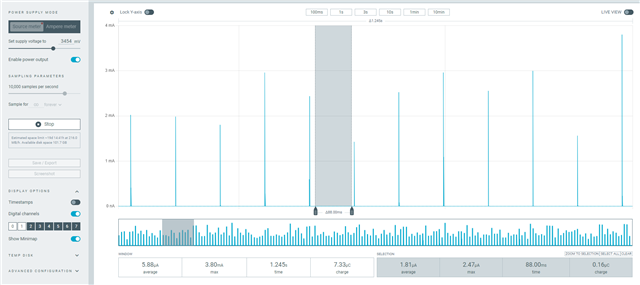
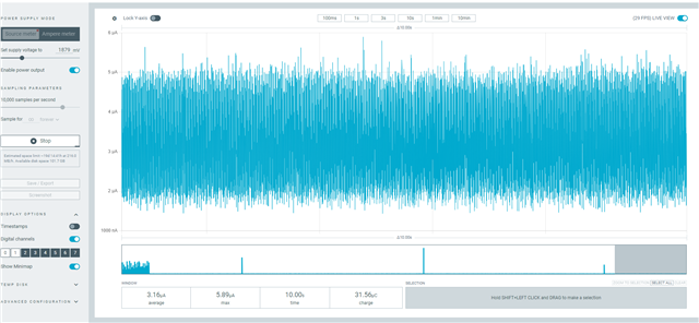
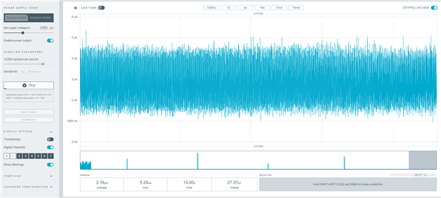
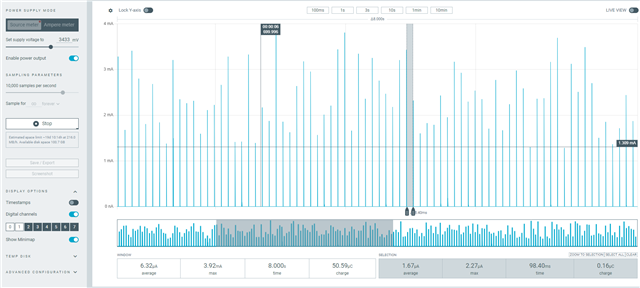
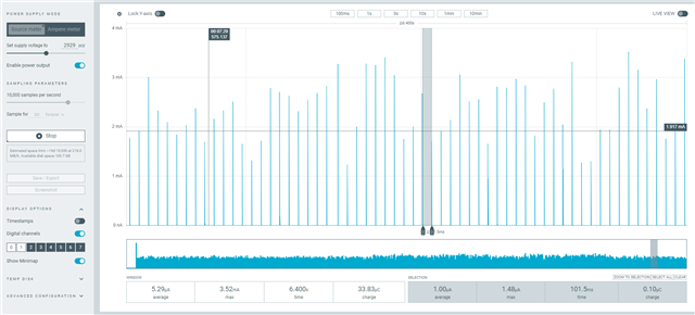
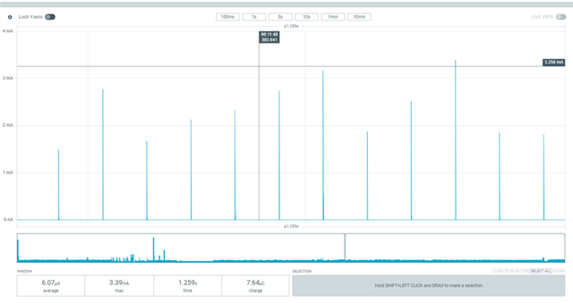
The power consumption tested was around 1uA, which should be normal according to the errata. Then, I wanted to test the idle state. Based on the above, I turned off the following content and tested that the power consumption was around 6uA.

This doesn't seem to match the specification book.

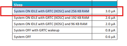
Is there any other way to test the power consumption of "System ON IDLE with GRTC (XOSC) and 256 KB RAM"?

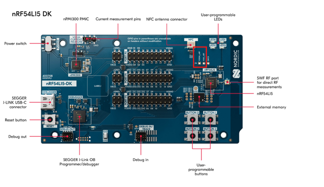
note:v2.8.0,NRF54L15,QFAABB

Parents Reply Children
  • The issues here are the spikes that you see all over the graph. They are not true spikes but rather false measurements due to limitations of the PPK.

    I don't always see this issue, but when I do, changing the voltage in small steps help me find a threshold where such spikes occur. That doesn't help you see the real current draw at 3.3V, but the idea is, you can see that as supply voltage increase, current should decrease. Beyond this, at 3.3V, you would have to zoom in and selectively measure between the spikes.

    I am asking internally what those spikes are and what can be done about them. I will get back to you once I get anything.

  • you can see that as supply voltage increase, current should decrease.

    From the graph, it appears to be limited to voltages below 3V?

    Beyond this, at 3.3V, you would have to zoom in and selectively measure between the spikes.

    Is this the first two images? Is the power consumption 1.8uA at this time

  • 666 said:
    Beyond this, at 3.3V, you would have to zoom in and selectively measure between the spikes.

    Is this the first two images? Is the power consumption 1.8uA at this time

    No this also seems wrong.

    Could you please measure VDDM and VDD_nRF with a voltmeter and let me know what the voltages are?

  • The two in the red box are both 3.43V.

    The two in the red box are both 2.93V.

  • I am trying to reproduce the issue on my end but haven't been able to yet. I only have earlier prototyping revisions of the DK, so I wonder if that is the difference. I will try to acquire a DK from the same revision as you.

    Meanwhile, could you please share what it looks like when you measure in Ampere Meter mode? With all three wires connected, that is.

    Do you also have a higher performance power analyzer, a different PPK, or a different nRF54L15 DK to switch up the setup? This is to help isolating where the problem is.

Related