nRF54L15-DK questions

Hi!

I am testing the nRF54L15-DK with 2.9.0 SDK and have some questions:

1. MX25R64:
  - why is it used in 1-bit (spi) and not 4-bit (qspi) mode? 
  - OTOH this setup saves some GPIO (but reduces speed). But why is the "spi-max-frequency" set to 8M (nrf54l_05_10_15_cpuapp_common.dtsi) when the chip datasheet says it can always do 32M or more?
  - is it a bad idea to not use CS pin (short it on flash chip side)? 
  - for the end product - should I use at least RESET pin so I can reboot the flash chip if needed?

2. Should RTT work with nRF54L15-DK? I have a project built with sysbuild and I am not able to make it work in the bootloader or in the app. My config is ok, I also upgraded J-Link to 8.12 which also upgraded the firmware on board debug MCU. Is there a test/example project that should work with nRF54L15-DK? Should RTT connection survive a reset after flash (or with a button)?

3. I know that you should not comment on new products, but I stumbled upon a DT for nRF54L20-PDK Slight smile
Will it have a RISC coprocessor? I am asking because it is not in PDK DT. I also see that it has 7 serial ports, which is great for me. Will it be part of the nRF54L 05-10-15-20 lineup or will it be a separate product?

Best regards,
Marko

Parents
  • Hi Marko,

    3. I know that you should not comment on new products, but I stumbled upon a DT for nRF54L20-PDK

    What we currently is avaiable as info on the L20 https://docs.nordicsemi.com/bundle/ncs-latest/page/zephyr/boards/nordic/nrf54l20pdk/doc/index.html , you will need to contact sales for more info.


    2. Should RTT work with nRF54L15-DK? I have a project built with sysbuild and I am not able to make it work in the bootloader or in the app. My config is ok, I also upgraded J-Link to 8.12 which also upgraded the firmware on board debug MCU. Is there a test/example project that should work with nRF54L15-DK? Should RTT connection survive a reset after flash (or with a button)?

    Yes RTT works, you can use some of the samples that we have like the radio test or blinky, https://docs.zephyrproject.org/3.7.0/samples/basic/blinky/README.html#blinky other BLE samples should also work. 

    This should do the be how to set it:

    CONFIG_USE_SEGGER_RTT=y
    CONFIG_RTT_CONSOLE=y
    CONFIG_UART_CONSOLE=n


    - for the end product - should I use at least RESET pin so I can reboot the flash chip if needed?

    Its always good to have a way to power cycle the device, so either with a reset or with disconnection of the power. Both will work. 


    - is it a bad idea to not use CS pin (short it on flash chip side)?

    It will depend on what you are using, if there is nothing else on the line and the master does not need to control it then tie it to active will release a pin from the master if that is needed.
     

    But why is the "spi-max-frequency" set to 8M (nrf54l_05_10_15_cpuapp_common.dtsi) when the chip datasheet says it can always do 32M or more?

    One high speed SPIM peripheral can do 32MHz, the rest has max 8MHz. 

    Regards,
    Jonathan

Reply
  • Hi Marko,

    3. I know that you should not comment on new products, but I stumbled upon a DT for nRF54L20-PDK

    What we currently is avaiable as info on the L20 https://docs.nordicsemi.com/bundle/ncs-latest/page/zephyr/boards/nordic/nrf54l20pdk/doc/index.html , you will need to contact sales for more info.


    2. Should RTT work with nRF54L15-DK? I have a project built with sysbuild and I am not able to make it work in the bootloader or in the app. My config is ok, I also upgraded J-Link to 8.12 which also upgraded the firmware on board debug MCU. Is there a test/example project that should work with nRF54L15-DK? Should RTT connection survive a reset after flash (or with a button)?

    Yes RTT works, you can use some of the samples that we have like the radio test or blinky, https://docs.zephyrproject.org/3.7.0/samples/basic/blinky/README.html#blinky other BLE samples should also work. 

    This should do the be how to set it:

    CONFIG_USE_SEGGER_RTT=y
    CONFIG_RTT_CONSOLE=y
    CONFIG_UART_CONSOLE=n


    - for the end product - should I use at least RESET pin so I can reboot the flash chip if needed?

    Its always good to have a way to power cycle the device, so either with a reset or with disconnection of the power. Both will work. 


    - is it a bad idea to not use CS pin (short it on flash chip side)?

    It will depend on what you are using, if there is nothing else on the line and the master does not need to control it then tie it to active will release a pin from the master if that is needed.
     

    But why is the "spi-max-frequency" set to 8M (nrf54l_05_10_15_cpuapp_common.dtsi) when the chip datasheet says it can always do 32M or more?

    One high speed SPIM peripheral can do 32MHz, the rest has max 8MHz. 

    Regards,
    Jonathan

Children
  • Hi Jonathan,

    Thank you for the answers. My comments (using 2.9.0 SDK on Windows):

    Ad 1) I was asking because on DK external flash is connected to spi00 (which is high speed). I am low on GPIO pins, so knowing that it is ok to use external flash on 4 pins (including reset, without CS) and 32M clock is valuable to me. I already changed the clock to 32M and flash still works.

    Ad 2) I can confirm that Blinky and my app work with RTT now (I did not test mcuboot yet). Perhaps I managed to break something before by using RTT "terminal" in VS code and JLink RTT Viewer at the same time? SHELL_BACKEND_RTT also works. However:
    - Reset breaks RTT connection. Can I do something to prevent this? It makes RTT unusable with mcuboot (at least for me), but I can also use uart console for mcuboot.
    - I needed to upgrade J-Link (to 8.14), otherwise J-Link said that my CPU is not supported. Now each time I start RTT "terminal" in VS code, it asks me for "Target device settings" because "NRF54L15_XXAA is unknown to this version of the J-Link software", then I need to manually select "nRF54L15_M33". Is this normal/expected?
    - Ideally, mcuboot, app console and app shell should use the same RTT address but different channels. Is this possible?

    Ad 3) I already know the answer I would get from sales Slight smile. It would help me because I am getting low on RAM with L15, but I will also need the coprocessor for a softdevice. Since PDK already exists I hope the release date is near. Until then: 
    - I did not try this yet, but is it possible to reserve less than 68 KB RAM for coprocessor on L15?

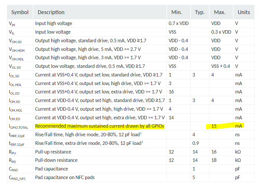
    4) Another question: I already changed the voltage to 3.3V for my DK. Can I power something that draws up to 1W from P30/P31/P32?

    Regards,
    Marko

Related