Using the LVGL sample... The sample LVGL code works on nrf52840dk but not the RAYTAC MDBT50Q. I hope I'm just missing something obvious?
- Flash blinking to nrf52840dk and RAYTAC MDBT50Q and both work (confirming jlink flash process/connections are good)
- I have to manually repower/reset the board on the MDBT50Q after flashing, so I do that
- flashing a LVGL sample, including led0 "on", to a nrf52840dk... works perfectly.
- flashing the exact same LVGL sample to a RAYTAC MDBT50Q (nrf52840) - doesn't work.
- led0, which is part of LVGL sample - doesn't work on MDBT50Q
- MDBT50Q appears to flash the LVGL sample correctly
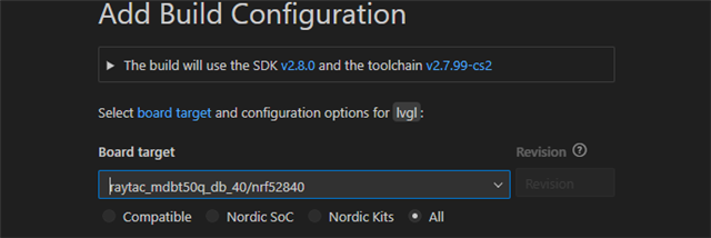
- command for both: west build -b nrf52840dk_nrf52840 -d build52840 -p -- -DSHIELD=waveshare_epaper_gdey0213b74
- I couldn't get a 0.97" OLED to work over SPI on the MDBT50Q
- I could get the I2c OLED version to work on the MDBT50Q.
- checked MDBT50Q pwr and gnd (3v3)
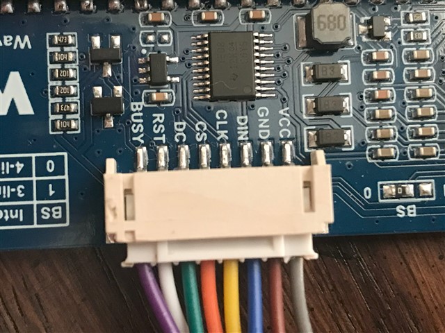
- I checked the SPI connections/reconnected many times
- The sample code and images: https://github.com/mej558/lvgl_Raytac_Question.git
- Included images and drawings in the repo folder /images.
- I tried 3 different waveshare displays of the same model. All work on the nrf52840dk, but not the MDBT50Q.
led0 does not come on when I flash LVGL to the MDBT50Q. However, if I pull gpio1.10(display reset) the led0 lights. If I then plug gpio1.10 back in led0 stays lit. Not sure what that means...
Thinking that there was something weird about gpio1.10 I modified the Waveshare shield to use gpio1.07:
With this change I get the same behavior that I had with gpio1.10, but now on gpio1.07: If I pull gpio1.07 led0 lights. Plug gpio1.07 in and led0 stays lit... With gpio1.10 or gpio1.07 the display never shows any activity/data/flashing/life, etc...
The gpio1.07 modification works perfectly on the nrf52840dk.


