GPIO pin value are read incorrectly from the .overlay file

I generated an overlay file with the following info:

// To get started, press Ctrl+Space to bring up the completion menu and view the available nodes.

// You can also use the buttons in the sidebar to perform actions on nodes.
// Actions currently available include:

// * Enabling / disabling the node
// * Adding the bus to a bus
// * Removing the node
// * Connecting ADC channels

// For more help, browse the DeviceTree documentation at https://docs.zephyrproject.org/latest/guides/dts/index.html
// You can also visit the nRF DeviceTree extension documentation at https://docs.nordicsemi.com/bundle/nrf-connect-vscode/page/guides/ncs_configure_app.html#devicetree-support-in-the-extension

&gpio0 {
	status = "okay";
};

&gpiote {
	status = "okay";
};

/ {
	leds {
		compatible = "gpio-leds";
		yellow_led: led {
			label = "led";
			gpios = <&gpio0 6 0>;
		};
	};
};

and there is my main.c file:

// have some useful utility functions provided by zeyphr kernal.
#include <zephyr/kernel.h>

// include the GPIO driver
#include <zephyr/drivers/gpio.h>

// get the gpio pin properties from the .overlay file
static struct gpio_dt_spec led = GPIO_DT_SPEC_GET(DT_NODELABEL(yellow_led), gpios);

int main(void)
{
        // check if the pin is ready to use (the function returns 0 if everything is ok)
        if(!gpio_is_ready_dt(&led))
        {
                // end the program
                return 0;
        }

        // check if the pin is configured successfully (the function returns 0 if everything is ok)
        if(gpio_pin_configure_dt(&led, GPIO_OUTPUT_INACTIVE) < 0)
        {
                // end the program
                return 0;
        }

        // loop infinitely
        while(1)
        {
                // toggle the led and check if it was toggled successfully 
                if(gpio_pin_toggle_dt(&led) < 0)
                {
                        return 0;
                }

                // sleep for 1 second 
                k_msleep(1000);
        }

        return 0;
}

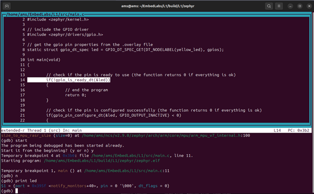
However, when I tried to debug my code to understand what was wrong, I got the following value of the led variable at the start of the main:

$1 = {port = 0x395f <notify_monitors+40>, pin = 0 '\000', dt_flags = 0}

which is incorrect because the pin value should be 6 not 0.

Parents
  • Hi,

    I do not see any issues with this, and when I test the code on my end, I see pin 6 toggling. Did you measure with alogic analyzer? Also, if you are testing on a DK (?) you may face problems as pin 6 is connected to the onboard debugger as UART TXD.

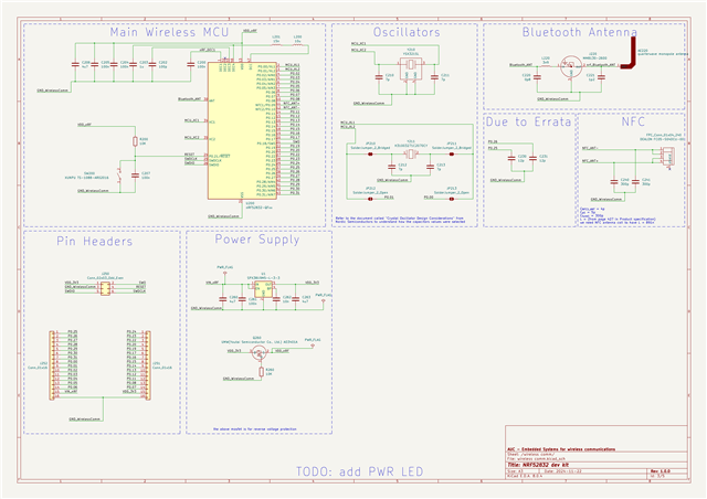
  • actually, it isn't working on my end and I am not using one of the Nordic development kits, I developed my kit and tried to run this code on it. here are the schematics:

    but I am pretty sure it has nothing to do with the hardware. I started a debugging session using the gdb server with the help of my black magic probe, and here is the CPU halted at the first line.


    before executing the first line, the variable called "led" is initialized to have a pin value equal to 0 which is incorrect because it's supposed to be 6. which means that the line 

    static struct gpio_dt_spec led = GPIO_DT_SPEC_GET(DT_NODELABEL(yellow_led), gpios);
    

    initializes the variable led with wrong values. I don't know why is that.

  • Hi,

    Could it be that you are missing CONFIG_GPIO=y in prj.conf or similar?

  • nothing changed. I am still trying to understand why. I am pretty sure it has something to do with the configuration files because I used the same blinky example code (which works with nrf52 dk configuration files) with my board configuration and it didn't work.

  • Now, I am having new behavior after clean build. the led variable pin field is set to 17 which is only defined in the 'nrf52 dk - nrf52832' board configuration files but I am using my board configuration files.

  • now after editing the code to be like this:

    #include <stdio.h>
    #include <zephyr/kernel.h>
    #include <zephyr/drivers/gpio.h>
    
    /* 1000 msec = 1 sec */
    #define SLEEP_TIME_MS   1000
    
    /* The devicetree node identifier for the "led0" alias. */
    #define LED23_NODE DT_ALIAS(led23)
    
    /*
     * A build error on this line means your board is unsupported.
     * See the sample documentation for information on how to fix this.
     */
    // DT_NODELABEL(led21)
    static const struct gpio_dt_spec led = GPIO_DT_SPEC_GET(LED23_NODE, gpios);
    
    int main(void)
    {
    	int ret;
    	bool led_state = true;
    
    	if (!gpio_is_ready_dt(&led)) {
    		return 0;
    	}
    
    	ret = gpio_pin_configure_dt(&led, GPIO_OUTPUT_ACTIVE);
    	if (ret < 0) {
    		return 0;
    	}
    
    	while (1) {
    		ret = gpio_pin_toggle_dt(&led);
    		if (ret < 0) {
    			return 0;
    		}
    		led_state = !led_state;
    		printf("LED state: %s\n", led_state ? "ON" : "OFF");
    		k_msleep(SLEEP_TIME_MS);
    	}
    	return 0;
    }

    and the .overlay file to be like this:

    // To get started, press Ctrl+Space to bring up the completion menu and view the available nodes.
    
    // You can also use the buttons in the sidebar to perform actions on nodes.
    // Actions currently available include:
    
    // * Enabling / disabling the node
    // * Adding the bus to a bus
    // * Removing the node
    // * Connecting ADC channels
    
    // For more help, browse the DeviceTree documentation at https://docs.zephyrproject.org/latest/guides/dts/index.html
    // You can also visit the nRF DeviceTree extension documentation at https://docs.nordicsemi.com/bundle/nrf-connect-vscode/page/guides/ncs_configure_app.html#devicetree-support-in-the-extension
    
    &gpio0 {
    	status = "okay";
    };
    
    &gpiote {
    	status = "okay";
    };
    
    
    / {
    	leds {
    		compatible = "gpio-leds";
    		led20: led21 {
    			label = "led";
    			gpios = <&gpio0 18 GPIO_ACTIVE_HIGH>;
    		};
        
    	};
    
    	aliases {
    		led23 = &led20;
    	};
    };
    

    I am getting a strange behavior that no matter what led21 gpio pin is defined to, it's always 17 during runtime and actually pin 17 is the one toggling on the actual hardware.

Reply
  • now after editing the code to be like this:

    #include <stdio.h>
    #include <zephyr/kernel.h>
    #include <zephyr/drivers/gpio.h>
    
    /* 1000 msec = 1 sec */
    #define SLEEP_TIME_MS   1000
    
    /* The devicetree node identifier for the "led0" alias. */
    #define LED23_NODE DT_ALIAS(led23)
    
    /*
     * A build error on this line means your board is unsupported.
     * See the sample documentation for information on how to fix this.
     */
    // DT_NODELABEL(led21)
    static const struct gpio_dt_spec led = GPIO_DT_SPEC_GET(LED23_NODE, gpios);
    
    int main(void)
    {
    	int ret;
    	bool led_state = true;
    
    	if (!gpio_is_ready_dt(&led)) {
    		return 0;
    	}
    
    	ret = gpio_pin_configure_dt(&led, GPIO_OUTPUT_ACTIVE);
    	if (ret < 0) {
    		return 0;
    	}
    
    	while (1) {
    		ret = gpio_pin_toggle_dt(&led);
    		if (ret < 0) {
    			return 0;
    		}
    		led_state = !led_state;
    		printf("LED state: %s\n", led_state ? "ON" : "OFF");
    		k_msleep(SLEEP_TIME_MS);
    	}
    	return 0;
    }

    and the .overlay file to be like this:

    // To get started, press Ctrl+Space to bring up the completion menu and view the available nodes.
    
    // You can also use the buttons in the sidebar to perform actions on nodes.
    // Actions currently available include:
    
    // * Enabling / disabling the node
    // * Adding the bus to a bus
    // * Removing the node
    // * Connecting ADC channels
    
    // For more help, browse the DeviceTree documentation at https://docs.zephyrproject.org/latest/guides/dts/index.html
    // You can also visit the nRF DeviceTree extension documentation at https://docs.nordicsemi.com/bundle/nrf-connect-vscode/page/guides/ncs_configure_app.html#devicetree-support-in-the-extension
    
    &gpio0 {
    	status = "okay";
    };
    
    &gpiote {
    	status = "okay";
    };
    
    
    / {
    	leds {
    		compatible = "gpio-leds";
    		led20: led21 {
    			label = "led";
    			gpios = <&gpio0 18 GPIO_ACTIVE_HIGH>;
    		};
        
    	};
    
    	aliases {
    		led23 = &led20;
    	};
    };
    

    I am getting a strange behavior that no matter what led21 gpio pin is defined to, it's always 17 during runtime and actually pin 17 is the one toggling on the actual hardware.

Children
No Data
Related