nRF5340 power consumption when using the nRF7002

Hello,

I am currently using two hardware:

1. nRF7002DK PCA10143

2. Fanstel WT02C40C that has the nRF5340 and nRF7002 pair. Here is the latest manual of this module.

In both scenarios, I have loaded the same firmware that enables an AP connection and a TWT session of 4.5 seconds. The main issue is related to the power consumption drawn by the entire nRF5340 and nRF7002 pair under different power supply cases. I am fully interested in the power consumption between sleep-time intervals between TWT pings.

Some conditions of the firmware:

1. DC/DC mode on the internal regulators (VREGMAIN, VREGH, VREGRADIO) are enabled.

2. CONFIG_SERIAL=n and CONFIG_LOG=n are applied to avoid high power consumption due to logging.

3. CONFIG_BOARD_ENABLE_CPUNET=n because the firmware does not use the Network Core. 

4. CONFIG_NRF_WIFI_LOW_POWER=y to ensure low power modes on nRF7002 chip

5. CONFIG_SOC_ENABLE_LFXO=y; CONFIG_SOC_LFXO_CAP_INT_7PF=y; CONFIG_SOC_HFXO_CAP_INTERNAL=y; CONFIG_SOC_HFXO_CAP_INT_VALUE_X2=25 when using the Fanstel module. I tested the consumption not considering those CONFIG tags, but no changes are achieved. 

6. CONFIG_BT=n, CONFIG_PM_DEVICE=y to ensure more directives for low power consumption.


Let me show you the following results. Each result has a raw diagram of the PPK connection in order to show the measurement connection:

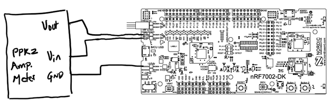
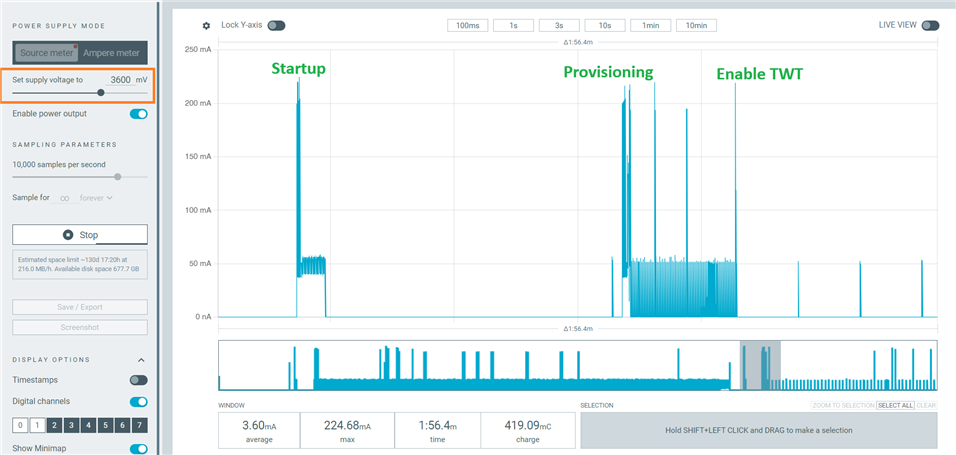
1. Test 1: Firmware loaded in the nRF7002DK that uses VDD at 1.8V (for the nRF5340) and VBAT (for the nRF7002 chip) at 3.3V. Here are presented separate consumption graphics with the PPK2 following the instructions of the Current Measurements on nRF7002DK

1.1. Separate consumption cases: Measurement of the current consumption of each chip. 

For the nRF5340 device:

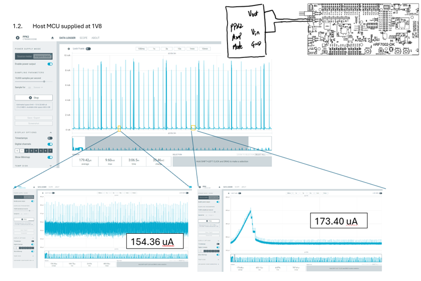
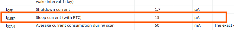
For the nRF7002 chip:

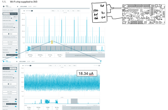
Adding the values at sleep mode, we can estimate a total consumption of the nRF5240 and nRF7002 pair as: 173.40uA + 18.34 uA = 191.74uA

Result 191.74uA 

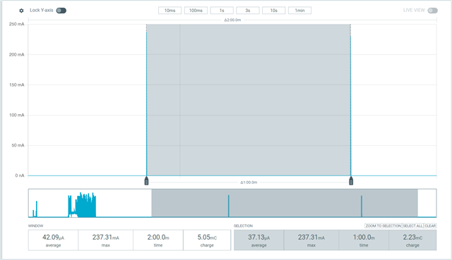
1.2. Complete Dev. Kit consumption: Measurement of the entire power consumption of the nRF7002DK --> Here, as the Dev Kit has other components that are connected to the power supply, (regulators, level detectors and so on, based on the PCA10143 Power supply schematic) it is expected that the consumption could increase.


Result: 1.8mA

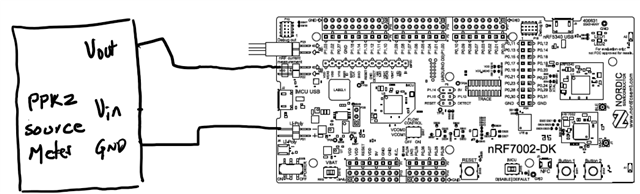
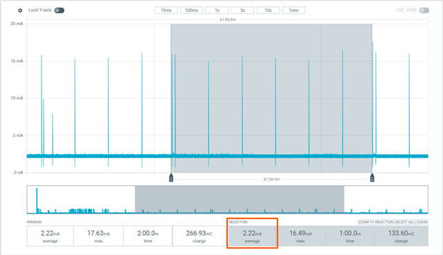
2. Test 2: Fanstel WT02C40C supplying the internal nRF5340 at 3.3V (High Voltage Mode with VDD disconnected and VDDH connected) and the nRF7002 at 3.3V. This schema follows one of the ways to supply the nRF5230 and nRF7002 pair shown here for the High Voltage Mode. The Fanstel module includes the external crystals too:
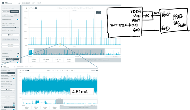
Result: 4.51 mA. 

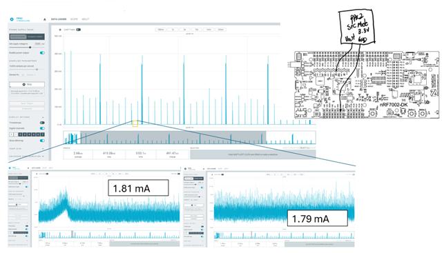
3. Test 3: Fanstel WT02C40C supplying the nRf5340 at 1.8V (both VDD and VDDH) and nRF7002 at 3V3 (VBat). It follows the Normal Voltage Mode on the nRF7002 reference shown here:

There are two cases:

3.1. When using a weak connection of the 1.8V regulator shown in the diagrams (using Dupont cables and protoboard) the results are the following after moving the connections or changing the cables:
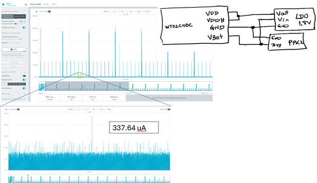
Result: 337.64 uA

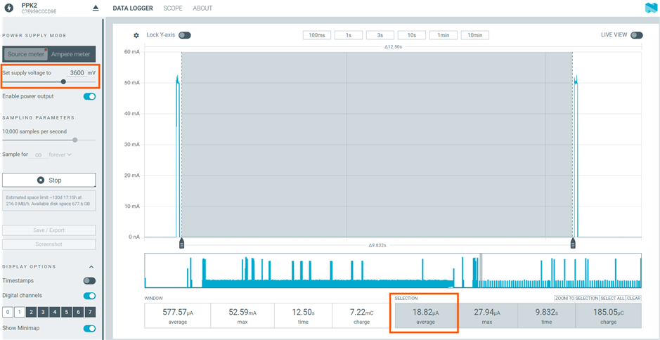
3.2. When soldering properly the regulator to the Fanstel module with suitable connection of the regulator
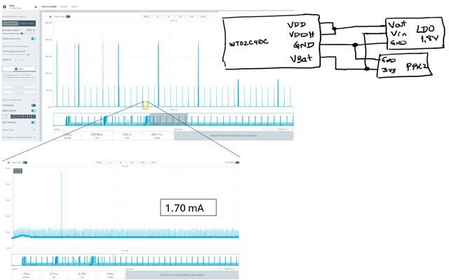
Result: 1.7mA

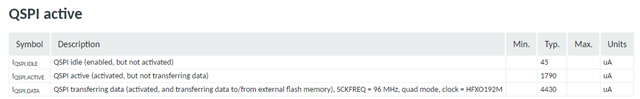
The main objective of this is to achieve the lowest power consumption of both the nRF5340 and nRF7002 devices. Since the power changes are applied on VDD and VDDH (related to the nRF5340), I suppose that the higher power consumption is entirely on the nRF5340 device. Looking its reference manual, I can see that when the QSPI is enabled in Idle mode (That could be the mode that is applied when the nRF7002 is in sleep mode in the times between TWT intervals), the consumption is less than in all cases shown here (the reference manual assumes a power supply on VDD and VDDH of 3V in Normal Voltage Mode when using the QSPI as shown here)


Could you help me to have a more insight about some missing configuration on the nRF5340, or any other support at hardware level I need to consider? The Fanstel module follows all the powering recommendations on the nRF5340-nRF7002 pair, similar as it is implemented on the nRF7002DK.   

  • Q1: You've added some configurations for the build of code, but which code example are you uploading to the devices when you are running the tests? Is the functionality the same when you run the full test on DK as on the Fanstel device?
    Q2: https://docs.nordicsemi.com/bundle/ncs-latest/page/nrf/app_dev/device_guides/nrf70/power_profiling.html It looks like you're using the PPK2 to deliver current but also measuring by using an ampere meter on various parts of the supply. The link here has a plot that shows average current consumed by the nRF7002 DK with TWT interval of 1min. It averages just below 30uA across a minute. Are you able to recreate this setup on your 7002-DK? This would be a good starting point.
    Q3: Are you actively switching off interfaces and putting the devices into low power mode for the tests on the Fanstel devices? You have selected 1.8V for the nRF5340 and running the nRF7002 at 3.3V, why are you running at different voltages?
    Try to recreate the setup and results from https://docs.nordicsemi.com/bundle/ncs-latest/page/nrf/app_dev/device_guides/nrf70/power_profiling.html as you have that kit already. Build the same code and compare it to the example.
    Best regards
    Asbjørn
  • Hi Asbjørn, Thank you for your reply.

    Answers for your questions:

    Q1: You've added some configurations for the build of code, but which code example are you uploading to the devices when you are running the tests? Is the functionality the same when you run the full test on DK as on the Fanstel device?

    Actually, it is not any nRF Connect SDK example. It is a custom firmware we are developing of our internal project. It establishes an AP connection and enables a TWT session with TWT Wake interval of 12 ms and TWT Interval of 4.5 seconds. The functionality is exactly the same and was tested on both the nRF7002DK and the Fanstel module. 

    Q2: https://docs.nordicsemi.com/bundle/ncs-latest/page/nrf/app_dev/device_guides/nrf70/power_profiling.html It looks like you're using the PPK2 to deliver current but also measuring by using an ampere meter on various parts of the supply. The link here has a plot that shows average current consumed by the nRF7002 DK with TWT interval of 1min. It averages just below 30uA across a minute. Are you able to recreate this setup on your 7002-DK? This would be a good starting point.

    In this ticket post, I only used the PPK2 as Source Meter to measure the consumption of the nRF5340 (Host MCU) and nRF7002 (Wi-Fi Chip) as a whole circuit.

    And of course. I loaded the Wi-Fi: Shell example with nRF Connect SDK v2.7.0, on the nRF7002DK here are the results measuring the current drawn by the nRF7002 chip. I followed the exact PPK2 connection and configuration mode as Source Meter with 3.6V shown in the same link. The results are quite similar.

    Q3: Are you actively switching off interfaces and putting the devices into low power mode for the tests on the Fanstel devices? You have selected 1.8V for the nRF5340 and running the nRF7002 at 3.3V, why are you running at different voltages?

    In the Fanstel module, the nRF5340 pins VDD and VDDH, and the nRF7002 VBAT are exposed to be connected in several ways following the maximum ratings of each chip. Therefore, I followed the nRF7002 Reference Manual (Supply alternatives) (Figure 16) that shows a 1.8V power supply to the Host MCU (nRF5340) and 3.3-3.6V to the VBAT on the nRF7002 device. The nRF7002DK in the PCA10143 schematic uses the same supply setup on both the nRF5340 and nRF7002 devices

    --------------------------------

    As you can see in the answer for Q2, the nRF7002 consumption is quite the same that you reference in the link you cited. However, I am fully interested in how to achieve the lowest power consumption on the nRF5340 device that controls the nRF7002 chip operation when the TWT session was established, specifically among TWT pings without shutting down the nRF7002 chip and instead, using only its SLEEP state.

    I have measured the power consumption of the nRF5340 device, applying the following PPK2 connections (quite the same that was indicated in the link you referenced, but measuring the nRF5340 instead of the nRF7002) on the nRF7002DK and the same Wi-Fi Shell example:


    And I have obtained the same outcome despite the way I connected and configured the PPK2. I am mainly focused between two TWT pings consumption:

    These results on the nRF5340 are quite high. Then, could you please guide me to get the lowest power consumption of the nRF5340 in the scenario I specified above?

  • Hi,
    "Connect the Vout on the PPK2 kit to the P23 pin 1 on the nRF7002 DK" from https://docs.nordicsemi.com/bundle/ncs-latest/page/nrf/app_dev/device_guides/nrf70/power_profiling.html
    From your pictures you seem to supply on P22. Is that correct?
    Powered by Zoomin Software. For more details please contactZoomin. Other Sites. Nordicsemi.com DevAcademy DevZone
    docs.nordicsemi.com
    There's an example and pictures on measuring current on a nRF7002-DK with TWT here: https://github.com/martelmy/NCS_examples/blob/main/wifi/twt_provisioning_demo/README.md
    The 2.22mA average you seem is indicating that the nRF5340 for debugging is not going to sleep/power down in between events. What's the nRF5350 doing in between the radio events in your code? Are you using the second nRF5340 for logging or active but still on the DK supply net?
    Best regards
    Asbjørn
  • Hi Asbjørn,

    Thank you for your response,

    Hi,
    "Connect the Vout on the PPK2 kit to the P23 pin 1 on the nRF7002 DK" from https://docs.nordicsemi.com/bundle/ncs-latest/page/nrf/app_dev/device_guides/nrf70/power_profiling.html
    From your pictures you seem to supply on P22. Is that correct?

    yes, since my goal is to measure the nRF5340 power consumption, I used the P22 rather than P23. The P23 is used to measure nRF7002 chip power consumption. The solder bridges SB16 and SB17 were modified as you cited, and I got the results you see in my previous response.

    -----------------------------------------------------------------------------------------------------------------

    The 2.22mA average you seem is indicating that the nRF5340 for debugging is not going to sleep/power down in between events. What's the nRF5350 doing in between the radio events in your code? Are you using the second nRF5340 for logging or active but still on the DK supply net?

    About the behavior among TWT radio events, I just used the Wi-FI Shell example, so I guess that the nRF5340 is not getting a sleep state despite I disabled the serial port logging with CONFIG_SERIAL=n in the same example.  

    -----------------------------------------------------------------------------------------

    There's an example and pictures on measuring current on a nRF7002-DK with TWT here: https://github.com/martelmy/NCS_examples/blob/main/wifi/twt_provisioning_demo/README.md

    In the same way, I followed all the steps you cited in the link https://github.com/martelmy/NCS_examples/blob/main/wifi/twt_provisioning_demo/README.md and I got the following results:

    1. Current measurement on the nRF7002 chip based on the following photo (same as shown in the link)
     
    And we got those results:

     
    When making a zoom between TWT intervals (between ping events) we have 18.82 uA (similar to the nRF7002 I_SLEEP value given in the reference manual Table 2):

    2. Current measurement for the nRF5340 device (Host MCU)
    In this case, we followed the documentation steps shown in Using two PPK2s to measure component current consumption in order to measure the consumption on the nRF5340 device, and using the same Firmware example you cited, we got the following result between TWT pings:
    Here is the photo of the connection where we measure only the nRF5340 consumption (please look for the solder jumpers SB16 and SB17 that follow the steps cited):
    As shown, we got the expected results for the nRF7002, but we would need the lowest possible power consumption of the nRF5340 side.
  • Hello,

    We've had some more people look into the questions you are seeing and it seems like it's an issue with our side combination of documentation and FW. We are working on updates to be released to described how to achieve the current measurements you want. I will keep you updated on the timeline for the changes we do and to notify you.

    Best regards

    Asbjørn

Related