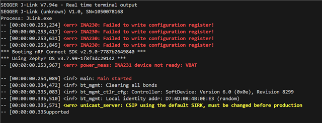
Issue related to running unicast server application on custom board.

Hi Nordic Team and Other,

We are evaluating an audio product using a NRF5340 Audio Dk (Custom Board) and using nrf5340 DK for flashing the custom board using the setup as mentioned below.

We are using v2.9.0 and referencing the unicast server application for testing purpose.

We are using following setup to program our custom board.
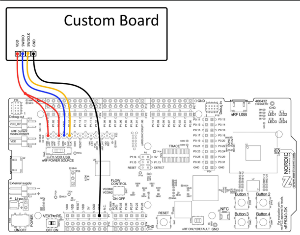
Currently, we are utilizing RTT for console messages instead of the serial port.

We are encountering issues and receiving error messages.
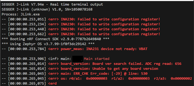
Please find attached the prj.conf file for the nRF audio application we are using.

2133.prj.conf

Could you kindly review the configuration and assist us in programming the custom board(this is based on the NRF5340 Audio DK)?

Thanks for your support.

  • Hi

    Despite disabling the I2C interface in the nrf5340dk_nrf5340_cpuapp.overlay, I'm still encountering errors related to the INA230/INA231 peripherals and ADC readings. Additionally, the RTT log output stalls after a few prints.

    My setup includes:

    • Custom Board: NRF5340-CLAA with CS47L63-CWZR DSP

    • Flashing Method: nRF5340 DK via P20 Debug Output Connector

    • Flashed Images: ipc_radio and nrf5340_audio

    • Board Target: nrf5340_audio_dk/nrf5340/cpuapp

    • IDE: Visual Studio Code with default settings

    Issues Faced:

    1. Persistent Peripheral Errors:

      • INA230/INA231 errors despite disabling I2C in the overlay.

      • ADC read register errors impacting board version detection.

    2. RTT Logging Limitations:

      • RTT logs halt after a few outputs, hindering debugging efforts.

    Request:

    • Guidance on properly adding custom board support, including necessary configurations to eliminate unwanted peripheral initialization.

    • Assistance in resolving RTT logging issues, ensuring continuous and reliable log output for debugging.

    Your expertise in this area would be immensely valuable in helping us overcome these challenges promptly.

    Thank you for your support.

  • Hi,

    Could you please refer us to the document and section where the ADC details are mentioned for getting the board version? 

        board_id: board_id {
            compatible = "voltage-divider";
            io-channels = <&adc 0>;
            output-ohms = <20000>;
            full-ohms = <47000>;
            power-gpios = <&gpio0 24 GPIO_ACTIVE_HIGH>;
        };
    In our case, we are getting an ADC value of 656, which is way beyond the tolerance value. It seems we have an incorrect ADC configuration.
    Also, please let us know the section where we can find details on the following configuration:
    arduino_i2c: &i2c1 {
        compatible = "nordic,nrf-twim";
        status = "okay";
        pinctrl-0 = <&i2c1_default>;
        pinctrl-1 = <&i2c1_sleep>;
        pinctrl-names = "default", "sleep";

        vbat_sensor: ina231@44 {
            compatible = "ti,ina230";
            reg = <0x44>;
            adc-mode = "Bus and shunt voltage continuous";
            vbus-conversion-time-us = <4156>;
            vshunt-conversion-time-us = <4156>;
            avg-count = <1024>;
            current-lsb-microamps = <1>;
            rshunt-micro-ohms = <510000>;
        };

        vdd1_codec_sensor: ina231@45 {
            compatible = "ti,ina230";
            reg = <0x45>;
            adc-mode = "Bus and shunt voltage continuous";
            vbus-conversion-time-us = <4156>;
            vshunt-conversion-time-us = <4156>;
            avg-count = <1024>;
            current-lsb-microamps = <1>;
            rshunt-micro-ohms = <2200000>;
        };

        vdd2_codec_sensor: ina231@41 {
            compatible = "ti,ina230";
            reg = <0x41>;
            adc-mode = "Bus and shunt voltage continuous";
            vbus-conversion-time-us = <4156>;
            vshunt-conversion-time-us = <4156>;
            avg-count = <1024>;
            current-lsb-microamps = <1>;
            rshunt-micro-ohms = <2200000>;
        };

        vdd2_nrf_sensor: ina231@40 {
            compatible = "ti,ina230";
            reg = <0x40>;
            adc-mode = "Bus and shunt voltage continuous";
            vbus-conversion-time-us = <4156>;
            vshunt-conversion-time-us = <4156>;
            avg-count = <1024>;
            current-lsb-microamps = <1>;
            rshunt-micro-ohms = <1000000>;
        };
    };
  • Hi,

    embdev61 said:

    Could you please refer us to the document and section where the ADC details are mentioned for getting the board version? 

        board_id: board_id {
            compatible = "voltage-divider";
            io-channels = <&adc 0>;
            output-ohms = <20000>;
            full-ohms = <47000>;
            power-gpios = <&gpio0 24 GPIO_ACTIVE_HIGH>;
        };

    Mentioned configuration can be found in nrf5340_audio_dk_nrf5340_cpuapp_common.dtsi file. The details can be found in the overview of the battery voltage measurement sample by pressing on "Explain this code" above the configuration.

    For details about ti,ina230, you can refer to ti,ina230 Zephyr dts bindings.

    Best regards,
    Dejan 


Related