Peripheral LBS not advertising with custom PCB (NCS V2.9.0)

As the title suggests, I am trying to run the peripheral LBS example on my custom PCB to test BLE before continuing with my application. I'm using NCS V2.9.0.

I have created a custom kConfig file enabling the internal RC clock at 500ppm (I do not have an external lfclk).
I also have a simple device tree overlay. Both are specified in the build config, the firmware builds and flashes successfully but I do not see the device advertising.

Things I've tried: 

- Different RC PPMs
- Testing on DK (works as expected)
- Changing GPIO in the overlay

Things I'm considering:
- Swap out the load caps on the 32M xtal
- Strip out the button and LED altogether

Any help is greatly appreciated. Schematic attached.

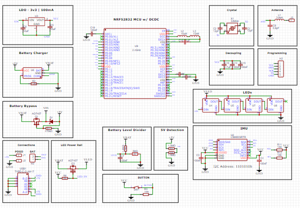
 8551.prj.confnrf52dk_nrf52832_cpuapp.overlay

  • Hi,

    Have you checked the log, so that you see if there are any errors or if it seems like everythign stared successfully? If not, we need to look into the errors you see from the log. If all look sgood there, there could be an issue with the HFXO. Either wrong load cap value (causing a frequency offset), or another typical issue is that the crystal may be rotated 90 degrees (then it will not start at all).

  • Thank you Einar. I have checked the log but see no errors. I was able to step through the entire application in debug mode at least once so it appears the application is starting up. I'm trying to check the RTT logs, however I'm unable to get them to print using Jlink RTT viewer (it seems to connect successfully). I can step over them in debug mode and believe I've set the configs correctly (I also set the build config to -Og)

    #
    # Copyright (c) 2018 Nordic Semiconductor
    #
    # SPDX-License-Identifier: LicenseRef-Nordic-5-Clause
    #
    CONFIG_NCS_SAMPLES_DEFAULTS=y
    
    CONFIG_BT=y
    CONFIG_BT_PERIPHERAL=y
    CONFIG_BT_DEVICE_NAME="Nordic_LBS"
    
    # Enable the LBS service
    CONFIG_BT_LBS=y
    CONFIG_BT_LBS_POLL_BUTTON=y
    CONFIG_DK_LIBRARY=y
    
    CONFIG_SYSTEM_WORKQUEUE_STACK_SIZE=2048
    
    # Use the internal RC oscillator for the 32 kHz LF clock
    CONFIG_CLOCK_CONTROL_NRF_K32SRC_RC=y
    CONFIG_CLOCK_CONTROL_NRF_K32SRC_500PPM=y
    
    # Enable system logging
    CONFIG_LOG=y
    CONFIG_LOG_DEFAULT_LEVEL=3
    
    # Enable RTT and make it the default console
    CONFIG_USE_SEGGER_RTT=y
    CONFIG_LOG_MODE_MINIMAL=n
    CONFIG_RTT_CONSOLE=y
    CONFIG_LOG_BACKEND_RTT=y
    #CONFIG_LOG_IMMEDIATE=y
    

  • I see. Which 32 MHz crystall are you using, and what is the load cap values?

    If you have access to a spectrum analyzer, could you check the frequency accuracy by setting up a carrier using the radio test sample and measurring the centrer frequency? Also, is the power decent, or not? If the frequency is off, we need to look at the crystal and load caps. If the power is low, we shoudl look at your hardware design (antenna and matching network in particular).

  • Here is the crystal I'm using: https://www.lcsc.com/datasheet/lcsc_datasheet_2403291505_YXC-Crystal-Oscillators-XL4EL89CMI-111YLC-32M_C18214312.pdf

    I see now that the ESR is quite high (150 max). I've tried several boards hoping one was at the lower end of tolerance - they do enter the application in debug mode so it appears that the crystal is starting up. Could this be a potential cause?

    I don't have access to an analyzer but I have used this layout in the past with a 1/4 wave antenna (albeit with an nrf51822 and the old sdk) and had no issues.  

    Thanks for your help. Also, any guess as to why RTT isn't printing?

  • Einar, following up here to close this out: I discovered that the load caps were not grounded Face palm. Attaching them to ground resulted in the device working as designed. Thanks for your help, time to go spin a new board!

Related