Hi,
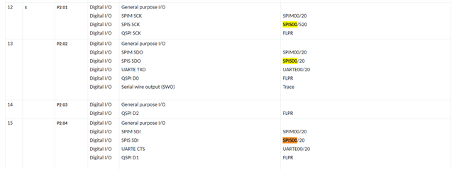
We developed our custom BLE electronic board based on the nRF54L15 SoC. On this project the nRF54L15 firmware setup a SPI slave interface in order to receive commands from a host MCU. All SPI lines are currently mapped on GPIO port P2. According to the nRF54L15 datasheet, I understand we have to use SPIS00 peripheral since it is the only one SPIS instance that can be mapped on this port without using dedicated pins.
The problem is this SPIS00 is not triggering any NRFX_SPIS_XFER_DONE event when receiving a SPI command from the host (looks like SPIS driver is not configured correctly).
In order to verify that this behavior isn't due to a hardware issue from our custom board, I realized the same test on the Nordic nRF54L15 DK board. Strangely I am able to communicate over SPI when selecting SPIS30 instance, but I doesn't work with SPIS00 too.
I used the following pins mapping on the Nordic nRF54L15 DK
| SPIS00 | SPIS30 | |
| MOSI Pin | P2.0 | P0.0 |
| MISO Pin | P2.1 | P0.1 |
| SCK Pin | P2.2 | P0.2 |
| CSN Pin | P2.3 | P0.3 |
To perform this test on the nRF54L15 DK I had to realize a couple of board settings / solder bridge configurations :
- I disabled UART0 through the Nordic Board Configuration tool to disconnect P0.0 to P0.3 from on-board debugger.
- I cut solder bridges SB11 to SB16 to disconnect P2.0 to P2.3 from QSPI flash memory and shortcut solder bridges SB17 to SB22 to connect P2.0 to P2.3 to the P2 GPIO connector.
On software side, I created a new application started from the nrfx_spim_spis Non-blocking example. I removed all part concerning SPIM driver.
I created a device tree overlay to support "nordic,nrf-spis" driver on both SPI00 and SPI30 peripherals and I enabled CONFIG_NRFX_SPIS00 and CONFIG_NRFX_SPIS30 configurations in prj.conf.
In the he nrfx_spim_spis Non-blocking example, SPIS pins mapping are directly declared inside the source code and doesn't use the pins description of the device tree. Looking deeper inside the Nordic nfx_spis library, I realized that the SPI pin number set inside the nrfx_spis_config_t structure shall combine the GPIO port number and the pin number (this is not really obvious in the structure description). So I used the NRF_GPIO_PIN_MAP() macro to declare these SPI pin numbers.
You can see on the SPI communication traces bellow that the nRF54L15 correctly returns the Tx buffer content when using SPIS30, but MISO line stay flat when using SPIS00 intance.
Any idea if I missed something in the project configuration ?
SPI transfer with SPIS30 instance![]()
SPI transfer with SPIS00 instance![]()