NRF52832 antena set-up

Hello,

I'm currently creating my own custom board for NRF 52832.

I put everything together, but I can't detect my custom board through Bluetooth using the NRF connect app. 

I'm using QFAA and QFAB QFN48 with DC/DC regulator setup.

Here I've attached the schematic of my custom board and all the components.

I'm new to designing an antenna for BLE. I believe there's something wrong with the antenna design. 

Please let me know if there's anything wrong with this design. 

Thank you!

Custom_nrf52832chip.pdf


  • Hello all, 

    I'm actually replying on behalf of Joseph, we work in the same lab. When we printed this circuit, the copper traces did seem to function as an antenna and we were able to establish a bluetooth connection. We assumed that this issue was resolved and this would continue to work, but we're now running into some additional problems. Mainly, it seems like all new circuits that we have printed (even using the exact same design file) are not able to establish a bluetooth connection. When we test them using a PPK, the working circuit is drawing upwards of 25mA whereas the other circuits are only drawing about 10mA, which I'm assuming is due to one being able to advertise and one not. We're looking into getting an antenna instead of using the copper traces, specifically the one found here. I guess I have two questions:

    1. Do you agree that the copper traces acting as an antenna are likely the issue here, given the power draw discrepancies and inability to connect over Bluetooth?

    2. If the antenna that we plan on purchasing would work, what would the best place to connect it be?

    Thank you for the help!

  • Can you use the radio test sample and check as well? 

    And you can use another DK with the RSSI viewer to check if it is outputting anything.


    Alternatively use this file, it puts the device in TX mode, unmodulated:
    nrf52 carrier ch40 4dBm (1).hex

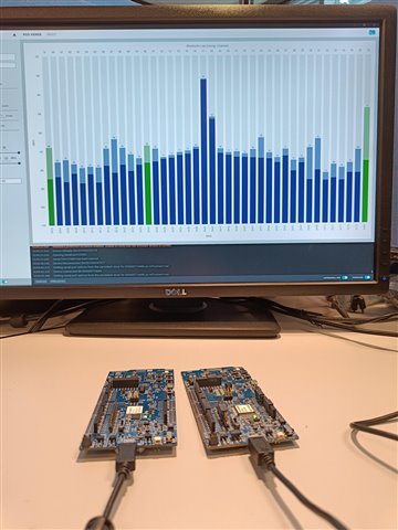
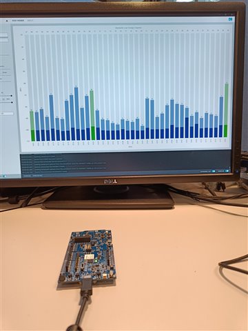
    Compare the current draw and check the RSSI viewer to see if a similar spike shows up. 


    Example image of a setup. 

    Regards,
    Jonathan

  • Hello Jonathan,

    To be perfectly honest, I don't fully understand your suggestions here. For one, I don't believe I can even connect my custom circuit to my laptop to use the RSSI viewer, since based on my understanding and your images it appears that a wired USB connection is required. When you suggest the radio test sample, is that meant to test whether it is a software or hardware issue? The code has not been updated, and works perfectly fine with the dk and with the older (completely identical to current design) model of our custom circuit. 

    The update since my last message is that we went ahead and purchased the antenna and manufactured the circuit using it. Now, the PPK shows a current draw of ~90mA, but still doesn't seem to be advertising over bluetooth. 

    Do you have any initial thoughts regarding the questions that I asked in the previous post, or do you need me to try and perform your recommended tests before you would be able to have a guess?

    Lastly, I'll attach the schematic of our current design. Thank you for the help.

    Regards,

    Connor S

    NASA research notes_250325_160255.pdf

  • connorshannon said:
    To be perfectly honest, I don't fully understand your suggestions here.

    Sorry for the poor description, let me try and clarify.

    In the image i shared here I use two DK's as example hardware, but only one is the used as the sensor\measuring unit. 

    So what I wanted you to do was to flash the example hex file i provided or use the radio test sample to your custom hardware. 

    Then use a DK with the RSSI viewer app to see if you see the custom HW show up as a spike. on the RSSI Viewer app. 

    I wanted to do this to see if there is a an issue with the radiated results. If there is no signal that shows up then its safe to guess that there si something wrong with the RF path or the antenna. 

    If you do get a strong signal then the issue might be sw related or it could be the 32MHz crystal, at least in many cases that is the case. 

    So this is what you can try, it might show a strong radiated peak, if that is the case you might be able to get some wireless communication but whitout propper equipment this will be extremely difficult to achieve. 

    But I have viewed the schematic before, and my previous comments still stand on that this design is unlikely to be able to have any successful radio communication.
    The design simply does not allow it.  

    2 layers is needed and the top and bottom copper ground planes needs to be connected. 
    Dedicated radio matching and dedicated antenna matching network is needed. 

    single copper plane will not do as there will be lots of issues with the return current path and grund loops for the system. 

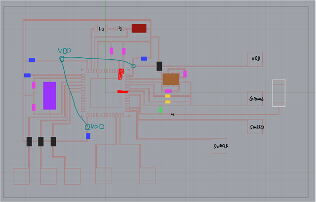
    I also want to add that you need to supply all the VDD pins with VDD, they need to be connected for the device to operate correctly. Not supplying VDD to all the VDD pins will put the device in a unstable state and things might work, or might not.  

    Regards,
    Jonathan


  • You need to add VDD on these sections. 

    Can be good to also have the red marked areas connected to ground. 

    But I recommend that you switch to KiCad or som other SW here to do the design, this will greatly help with the design process. There are also some relatively inexpensive PCB manufacturers like PCBway and JLCPCB that we have seen some customers use to make some designs.

    Regards,
    Jonathan

Related