Hi
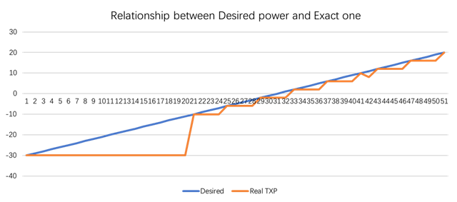
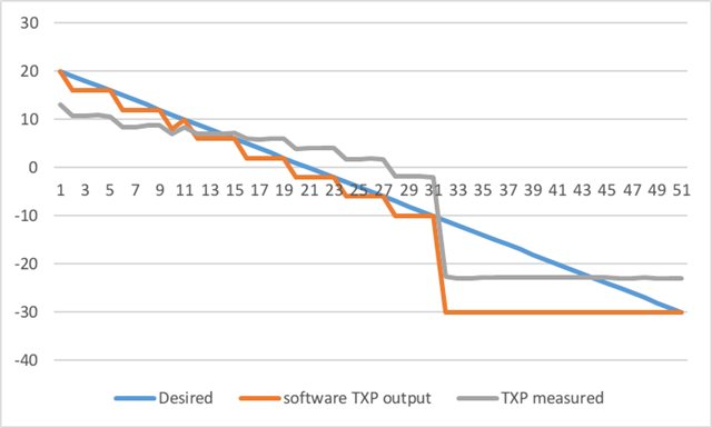
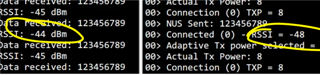
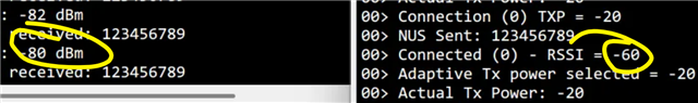
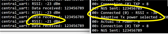
I am using HCI Power Control sample to dynamically control TX power. I found that the TX side's connection RSSI and RX side's are diferent, at some point it even has 20 db difference! Which one is the correct one?
My TX code:
/* main.c - Application main entry point */

/*
 * Copyright (c) 2019 Andrei Stoica
 *
 * SPDX-License-Identifier: Apache-2.0
 */

#include <zephyr/types.h>
#include <stddef.h>
#include <zephyr/sys/printk.h>
#include <zephyr/sys/util.h>
#include <zephyr/sys/byteorder.h>

#include <zephyr/bluetooth/bluetooth.h>
#include <zephyr/bluetooth/hci.h>
#include <zephyr/bluetooth/hci_vs.h>

#include <zephyr/bluetooth/conn.h>
#include <zephyr/bluetooth/uuid.h>
#include <zephyr/bluetooth/gatt.h>
//#include <zephyr/bluetooth/services/hrs.h>
#include <bluetooth/services/nus.h>

static struct bt_conn *default_conn;
static uint16_t default_conn_handle;

#define DEVICE_NAME         CONFIG_BT_DEVICE_NAME
#define DEVICE_NAME_LEN     (sizeof(DEVICE_NAME) - 1)

/* 虚拟命令字符串 */
static const char cmd_str[] = "123456789";


/* Advertising 数据 */
static const struct bt_data ad[] = {
    BT_DATA_BYTES(BT_DATA_FLAGS, (BT_LE_AD_GENERAL | BT_LE_AD_NO_BREDR)),
    BT_DATA(BT_DATA_NAME_COMPLETE, DEVICE_NAME, DEVICE_NAME_LEN),
};

static const struct bt_data sd[] = {
    BT_DATA_BYTES(BT_DATA_UUID128_ALL, BT_UUID_NUS_VAL),
};


#define DEVICE_BEACON_TXPOWER_NUM  8

static struct k_thread pwr_thread_data;
static K_THREAD_STACK_DEFINE(pwr_thread_stack, 512);

static const int8_t txpower[DEVICE_BEACON_TXPOWER_NUM] = {4, 0, -3, -8,
							  -15, -18, -23, -30};
static const struct bt_le_adv_param *param =
	BT_LE_ADV_PARAM(BT_LE_ADV_OPT_CONNECTABLE | BT_LE_ADV_OPT_ONE_TIME, 0x0020, 0x0020, NULL);


	/* NUS 收到数据回调 */
static void bt_receive_cb(struct bt_conn *conn, const uint8_t *const data, uint16_t len)
{
    printk("NUS Received: %.*s\n", len, data);
}

/* NUS 回调结构 */
static struct bt_nus_cb nus_cb = {
    .received = bt_receive_cb,
};


/* 定时发送函数 */
static void nus_notify(void)
{
    if (default_conn) {
        int err = bt_nus_send(default_conn, cmd_str, sizeof(cmd_str) - 1);
        if (err == -ENOMEM) {
            printk("Failed to send NUS data: Out of memory (err %d)\n", err);
        } else if (err) {
            printk("Failed to send NUS data (err %d)\n", err);
        } else {
            printk("NUS Sent: %s\n", cmd_str);
        }
    } else {
        printk("No active connection, skipping send\n");
    }
}


static void read_conn_rssi(uint16_t handle, int8_t *rssi)
{
	struct net_buf *buf, *rsp = NULL;
	struct bt_hci_cp_read_rssi *cp;
	struct bt_hci_rp_read_rssi *rp;

	int err;

	buf = bt_hci_cmd_create(BT_HCI_OP_READ_RSSI, sizeof(*cp));
	if (!buf) {
		printk("Unable to allocate command buffer\n");
		return;
	}

	cp = net_buf_add(buf, sizeof(*cp));
	cp->handle = sys_cpu_to_le16(handle);

	err = bt_hci_cmd_send_sync(BT_HCI_OP_READ_RSSI, buf, &rsp);
	if (err) {
		printk("Read RSSI err: %d\n", err);
		return;
	}

	rp = (void *)rsp->data;
	*rssi = rp->rssi;

	net_buf_unref(rsp);
}


static void set_tx_power(uint8_t handle_type, uint16_t handle, int8_t tx_pwr_lvl)
{
	struct bt_hci_cp_vs_write_tx_power_level *cp;
	struct bt_hci_rp_vs_write_tx_power_level *rp;
	struct net_buf *buf, *rsp = NULL;
	int err;

	buf = bt_hci_cmd_create(BT_HCI_OP_VS_WRITE_TX_POWER_LEVEL,
				sizeof(*cp));
	if (!buf) {
		printk("Unable to allocate command buffer\n");
		return;
	}

	cp = net_buf_add(buf, sizeof(*cp));
	cp->handle = sys_cpu_to_le16(handle);
	cp->handle_type = handle_type;
	cp->tx_power_level = tx_pwr_lvl;

	err = bt_hci_cmd_send_sync(BT_HCI_OP_VS_WRITE_TX_POWER_LEVEL,
				   buf, &rsp);
	if (err) {
		printk("Set Tx power err: %d\n", err);
		return;
	}

	rp = (void *)rsp->data;
	printk("Actual Tx Power: %d\n", rp->selected_tx_power);

	net_buf_unref(rsp);
}

static void get_tx_power(uint8_t handle_type, uint16_t handle, int8_t *tx_pwr_lvl)
{
	struct bt_hci_cp_vs_read_tx_power_level *cp;
	struct bt_hci_rp_vs_read_tx_power_level *rp;
	struct net_buf *buf, *rsp = NULL;
	int err;

	*tx_pwr_lvl = 0xFF;
	buf = bt_hci_cmd_create(BT_HCI_OP_VS_READ_TX_POWER_LEVEL,
				sizeof(*cp));
	if (!buf) {
		printk("Unable to allocate command buffer\n");
		return;
	}

	cp = net_buf_add(buf, sizeof(*cp));
	cp->handle = sys_cpu_to_le16(handle);
	cp->handle_type = handle_type;

	err = bt_hci_cmd_send_sync(BT_HCI_OP_VS_READ_TX_POWER_LEVEL,
				   buf, &rsp);
	if (err) {
		printk("Read Tx power err: %d\n", err);
		return;
	}

	rp = (void *)rsp->data;
	*tx_pwr_lvl = rp->tx_power_level;

	net_buf_unref(rsp);
}

static void connected(struct bt_conn *conn, uint8_t err)
{
	char addr[BT_ADDR_LE_STR_LEN];
	int8_t txp;
	int ret;

	if (err) {
		printk("Connection failed, err 0x%02x %s\n", err, bt_hci_err_to_str(err));
	} else {
		default_conn = bt_conn_ref(conn);
		ret = bt_hci_get_conn_handle(default_conn,
					     &default_conn_handle);
		if (ret) {
			printk("No connection handle (err %d)\n", ret);
		} else {
			/* Send first at the default selected power */
			bt_addr_le_to_str(bt_conn_get_dst(conn),
							  addr, sizeof(addr));
			printk("Connected via connection (%d) at %s\n",
			       default_conn_handle, addr);
			get_tx_power(BT_HCI_VS_LL_HANDLE_TYPE_CONN,
				     default_conn_handle, &txp);
			printk("Connection (%d) - Initial Tx Power = %d\n",
			       default_conn_handle, txp);

			set_tx_power(BT_HCI_VS_LL_HANDLE_TYPE_CONN,
				     default_conn_handle,
				     BT_HCI_VS_LL_TX_POWER_LEVEL_NO_PREF);
			get_tx_power(BT_HCI_VS_LL_HANDLE_TYPE_CONN,
				     default_conn_handle, &txp);
			printk("Connection (%d) - Tx Power = %d\n",
			       default_conn_handle, txp);
		}
	}
}

static void disconnected(struct bt_conn *conn, uint8_t reason)
{
	printk("Disconnected, reason 0x%02x %s\n", reason, bt_hci_err_to_str(reason));

	if (default_conn) {
		bt_conn_unref(default_conn);
		default_conn = NULL;
	}
}

BT_CONN_CB_DEFINE(conn_callbacks) = {
	.connected = connected,
	.disconnected = disconnected,
};

static void bt_ready(int err)
{
	if (err) {
		printk("Bluetooth init failed (err %d)\n", err);
		return;
	}

	printk("Bluetooth initialized\n");

	/* Start advertising */
	err = bt_le_adv_start(param, ad, ARRAY_SIZE(ad),
			      sd, ARRAY_SIZE(sd));
	if (err) {
		printk("Advertising failed to start (err %d)\n", err);
		return;
	}

	printk("Dynamic Tx power Beacon started\n");
}


void modulate_tx_power(void *p1, void *p2, void *p3)
{
	int8_t txp_get = 0;
	uint8_t idx = 0;

	while (1) {
		if (!default_conn) {
			printk("Set Tx power level to %d\n", txpower[idx]);
			set_tx_power(BT_HCI_VS_LL_HANDLE_TYPE_ADV,
				     0, txpower[idx]);

			k_sleep(K_SECONDS(5));

			printk("Get Tx power level -> ");
			get_tx_power(BT_HCI_VS_LL_HANDLE_TYPE_ADV,
				     0, &txp_get);
			printk("TXP = %d\n", txp_get);

			idx = (idx+1) % DEVICE_BEACON_TXPOWER_NUM;
		} else {
			int8_t rssi = 0xFF;
			int8_t txp_adaptive;

			idx = 0;

			read_conn_rssi(default_conn_handle, &rssi);
			printk("Connected (%d) - RSSI = %d\n",
			       default_conn_handle, rssi);
			if (rssi > -70) {
				txp_adaptive = -20;
			} else if (rssi > -90) {
				txp_adaptive = -12;
			} else {
				txp_adaptive = -4;
			}
			printk("Adaptive Tx power selected = %d\n",
			       txp_adaptive);
			set_tx_power(BT_HCI_VS_LL_HANDLE_TYPE_CONN,
				     default_conn_handle, txp_adaptive);
			get_tx_power(BT_HCI_VS_LL_HANDLE_TYPE_CONN,
				     default_conn_handle, &txp_get);
			printk("Connection (%d) TXP = %d\n",
			       default_conn_handle, txp_get);

			k_sleep(K_SECONDS(1));
		}
	}
}

int main(void)
{
	int8_t txp_get = 0xFF;
	int err;

	default_conn = NULL;
	printk("Starting Dynamic Tx Power Beacon Demo\n");

	/* Initialize the Bluetooth Subsystem */
	err = bt_enable(bt_ready);
	if (err) {
		printk("Bluetooth init failed (err %d)\n", err);
	}

	err = bt_nus_init(&nus_cb);
    if (err) {
        printk("Failed to initialize NUS (err %d)\n", err);
        return err;
    }

	printk("Get Tx power level ->");
	get_tx_power(BT_HCI_VS_LL_HANDLE_TYPE_ADV, 0, &txp_get);
	printk("-> default TXP = %d\n", txp_get);

	/* Wait for 5 seconds to give a chance users/testers
	 * to check that default Tx power is indeed the one
	 * selected in Kconfig.
	 */
	k_sleep(K_SECONDS(5));

	k_thread_create(&pwr_thread_data, pwr_thread_stack,
			K_THREAD_STACK_SIZEOF(pwr_thread_stack),
			modulate_tx_power, NULL, NULL, NULL,
			K_PRIO_COOP(10),
			0, K_NO_WAIT);
	k_thread_name_set(&pwr_thread_data, "DYN TX");

	while (1) {
		// hrs_notify();
		nus_notify();
		k_sleep(K_SECONDS(1));

	}
	return 0;
}
My RX code:
/*
 * Copyright (c) 2018 Nordic Semiconductor ASA
 *
 * SPDX-License-Identifier: LicenseRef-Nordic-5-Clause
 */

/** @file
 *  @brief Nordic UART Service Client sample
 */

#include <errno.h>
#include <zephyr/kernel.h>
#include <zephyr/device.h>
#include <zephyr/devicetree.h>
#include <zephyr/sys/byteorder.h>
#include <zephyr/sys/printk.h>

#include <zephyr/bluetooth/bluetooth.h>
#include <zephyr/bluetooth/hci.h>
#include <zephyr/bluetooth/conn.h>
#include <zephyr/bluetooth/uuid.h>
#include <zephyr/bluetooth/gatt.h>

#include <bluetooth/services/nus.h>
#include <bluetooth/services/nus_client.h>
#include <bluetooth/gatt_dm.h>
#include <bluetooth/scan.h>

#include <zephyr/settings/settings.h>

#include <zephyr/drivers/uart.h>

#include <zephyr/logging/log.h>

#include <zephyr/bluetooth/hci.h>


#define LOG_MODULE_NAME central_uart
LOG_MODULE_REGISTER(LOG_MODULE_NAME);

/* UART payload buffer element size. */
#define UART_BUF_SIZE 45

#define KEY_PASSKEY_ACCEPT DK_BTN1_MSK
#define KEY_PASSKEY_REJECT DK_BTN2_MSK

#define NUS_WRITE_TIMEOUT K_MSEC(150)
#define UART_WAIT_FOR_BUF_DELAY K_MSEC(50)
#define UART_RX_TIMEOUT 50000 /* Wait for RX complete event time in microseconds. */

static const struct device *uart = DEVICE_DT_GET(DT_CHOSEN(nordic_nus_uart));
static struct k_work_delayable uart_work;

K_SEM_DEFINE(nus_write_sem, 0, 1);

struct uart_data_t {
	void *fifo_reserved;
	uint8_t  data[UART_BUF_SIZE];
	uint16_t len;
};

static K_FIFO_DEFINE(fifo_uart_tx_data);
static K_FIFO_DEFINE(fifo_uart_rx_data);

static struct bt_conn *default_conn;
static struct bt_nus_client nus_client;


static char last_received_data[UART_BUF_SIZE] = {0};
static uint16_t last_received_data_len = 0;
static struct k_work_delayable rssi_work;

// static void rssi_work_handler(struct k_work *work)
// {
//     struct bt_conn_info info;
//     struct net_buf *buf = NULL, *rsp = NULL;
//     struct bt_hci_cp_read_rssi *cp;
//     struct bt_hci_rp_read_rssi *rp;
//     int err;

// 	if (default_conn) {
//         struct bt_conn_info info;
//         int err;

//         // 获取当前连接信息
//         err = bt_conn_get_info(default_conn, &info);
//         if (err) {
//             LOG_ERR("Failed to get connection info (err %d)", err);
//             return;
//         }

//         // 创建HCI命令缓冲区以读取RSSI
//         struct net_buf *buf = bt_hci_cmd_create(BT_HCI_OP_READ_RSSI, sizeof(uint16_t));
//         if (!buf) {
//             LOG_ERR("Failed to create HCI command buffer");
//             return;
//         }

//         // 填充HCI命令
//         struct bt_hci_cp_read_rssi *cp = net_buf_add(buf, sizeof(*cp));
//         cp->handle = sys_cpu_to_le16(info.id);

//         // 发送命令并解析响应
//         struct net_buf *rsp;
//         err = bt_hci_cmd_send_sync(BT_HCI_OP_READ_RSSI, buf, &rsp);
//         if (err) {
//             LOG_ERR("Failed to read RSSI (err %d)", err);
//             return;
//         }

//         struct bt_hci_rp_read_rssi *rp = (void *)rsp->data;
//         LOG_INF("RSSI: %d dBm", rp->rssi);
// 		LOG_INF("Data received: %.*s", last_received_data_len, last_received_data);

//         net_buf_unref(rsp);
//     }

//     // 调度下一次任务
//     k_work_reschedule(&rssi_work, K_SECONDS(1));  // 每秒读取一次RSSI
// }
static void rssi_work_handler(struct k_work *work)
{
    struct bt_conn_info info;
    struct net_buf *buf = NULL, *rsp = NULL;
    struct bt_hci_cp_read_rssi *cp;
    struct bt_hci_rp_read_rssi *rp;
    int err;

    if (!default_conn) {
        LOG_ERR("No default connection available");
        goto schedule;
    }

    /* 获取当前连接信息 */
    err = bt_conn_get_info(default_conn, &info);
    if (err) {
        LOG_ERR("Failed to get connection info (err %d)", err);
        goto schedule;
    }

    /* 创建 HCI 命令缓冲区以读取 RSSI */
    buf = bt_hci_cmd_create(BT_HCI_OP_READ_RSSI, sizeof(*cp));
    if (!buf) {
        LOG_ERR("Unable to allocate HCI command buffer");
        goto schedule;
    }

    /* 填充 HCI 命令数据(使用连接标识 info.id 作为句柄) */
    cp = net_buf_add(buf, sizeof(*cp));
    cp->handle = sys_cpu_to_le16(info.id);

    /* 发送 HCI 命令并等待同步响应 */
    err = bt_hci_cmd_send_sync(BT_HCI_OP_READ_RSSI, buf, &rsp);
    if (err) {
        LOG_ERR("Read RSSI error: %d", err);
        goto schedule;
    }

    /* 解析并打印 RSSI 数据 */
    rp = (void *)rsp->data;
    LOG_INF("RSSI: %d dBm", rp->rssi);
	LOG_INF("Data received: %.*s", last_received_data_len, last_received_data);

    net_buf_unref(rsp);

schedule:
    /* 调度下一次任务:每秒读取一次 RSSI */
    k_work_reschedule(&rssi_work, K_SECONDS(1));
}


static void ble_data_sent(struct bt_nus_client *nus, uint8_t err,
					const uint8_t *const data, uint16_t len)
{
	ARG_UNUSED(nus);
	ARG_UNUSED(data);
	ARG_UNUSED(len);

	k_sem_give(&nus_write_sem);

	if (err) {
		LOG_WRN("ATT error code: 0x%02X", err);
	}
}

// static uint8_t ble_data_received(struct bt_nus_client *nus,
// 						const uint8_t *data, uint16_t len)
// {
// 	ARG_UNUSED(nus);

// 	int err;

// 	for (uint16_t pos = 0; pos != len;) {
// 		struct uart_data_t *tx = k_malloc(sizeof(*tx));

// 		if (!tx) {
// 			LOG_WRN("Not able to allocate UART send data buffer");
// 			return BT_GATT_ITER_CONTINUE;
// 		}

// 		/* Keep the last byte of TX buffer for potential LF char. */
// 		size_t tx_data_size = sizeof(tx->data) - 1;

// 		if ((len - pos) > tx_data_size) {
// 			tx->len = tx_data_size;
// 		} else {
// 			tx->len = (len - pos);
// 		}

// 		memcpy(tx->data, &data[pos], tx->len);

// 		pos += tx->len;

// 		/* Append the LF character when the CR character triggered
// 		 * transmission from the peer.
// 		 */
// 		if ((pos == len) && (data[len - 1] == '\r')) {
// 			tx->data[tx->len] = '\n';
// 			tx->len++;
// 		}

// 		err = uart_tx(uart, tx->data, tx->len, SYS_FOREVER_MS);
// 		if (err) {
// 			k_fifo_put(&fifo_uart_tx_data, tx);
// 		}
// 	}

// 	return BT_GATT_ITER_CONTINUE;
// }


static uint8_t ble_data_received(struct bt_nus_client *nus,
                                 const uint8_t *data, uint16_t len)
{
    ARG_UNUSED(nus);

    // 保存接收到的数据
    memset(last_received_data, 0, sizeof(last_received_data));
    last_received_data_len = len < UART_BUF_SIZE ? len : UART_BUF_SIZE - 1;
    memcpy(last_received_data, data, last_received_data_len);

    //LOG_INF("Data received: %.*s", last_received_data_len, last_received_data);

    return BT_GATT_ITER_CONTINUE;
}


static void uart_cb(const struct device *dev, struct uart_event *evt, void *user_data)
{
	ARG_UNUSED(dev);

	static size_t aborted_len;
	struct uart_data_t *buf;
	static uint8_t *aborted_buf;
	static bool disable_req;

	switch (evt->type) {
	case UART_TX_DONE:
		LOG_DBG("UART_TX_DONE");
		if ((evt->data.tx.len == 0) ||
		    (!evt->data.tx.buf)) {
			return;
		}

		if (aborted_buf) {
			buf = CONTAINER_OF(aborted_buf, struct uart_data_t,
					   data[0]);
			aborted_buf = NULL;
			aborted_len = 0;
		} else {
			buf = CONTAINER_OF(evt->data.tx.buf,
					   struct uart_data_t,
					   data[0]);
		}

		k_free(buf);

		buf = k_fifo_get(&fifo_uart_tx_data, K_NO_WAIT);
		if (!buf) {
			return;
		}

		if (uart_tx(uart, buf->data, buf->len, SYS_FOREVER_MS)) {
			LOG_WRN("Failed to send data over UART");
		}

		break;

	case UART_RX_RDY:
		LOG_DBG("UART_RX_RDY");
		buf = CONTAINER_OF(evt->data.rx.buf, struct uart_data_t, data[0]);
		buf->len += evt->data.rx.len;

		if (disable_req) {
			return;
		}

		if ((evt->data.rx.buf[buf->len - 1] == '\n') ||
		    (evt->data.rx.buf[buf->len - 1] == '\r')) {
			disable_req = true;
			uart_rx_disable(uart);
		}

		break;

	case UART_RX_DISABLED:
		LOG_DBG("UART_RX_DISABLED");
		disable_req = false;

		buf = k_malloc(sizeof(*buf));
		if (buf) {
			buf->len = 0;
		} else {
			LOG_WRN("Not able to allocate UART receive buffer");
			k_work_reschedule(&uart_work, UART_WAIT_FOR_BUF_DELAY);
			return;
		}

		uart_rx_enable(uart, buf->data, sizeof(buf->data),
			       UART_RX_TIMEOUT);

		break;

	case UART_RX_BUF_REQUEST:
		LOG_DBG("UART_RX_BUF_REQUEST");
		buf = k_malloc(sizeof(*buf));
		if (buf) {
			buf->len = 0;
			uart_rx_buf_rsp(uart, buf->data, sizeof(buf->data));
		} else {
			LOG_WRN("Not able to allocate UART receive buffer");
		}

		break;

	case UART_RX_BUF_RELEASED:
		LOG_DBG("UART_RX_BUF_RELEASED");
		buf = CONTAINER_OF(evt->data.rx_buf.buf, struct uart_data_t,
				   data[0]);

		if (buf->len > 0) {
			k_fifo_put(&fifo_uart_rx_data, buf);
		} else {
			k_free(buf);
		}

		break;

	case UART_TX_ABORTED:
		LOG_DBG("UART_TX_ABORTED");
		if (!aborted_buf) {
			aborted_buf = (uint8_t *)evt->data.tx.buf;
		}

		aborted_len += evt->data.tx.len;
		buf = CONTAINER_OF(aborted_buf, struct uart_data_t,
				   data[0]);

		uart_tx(uart, &buf->data[aborted_len],
			buf->len - aborted_len, SYS_FOREVER_MS);

		break;

	default:
		break;
	}
}

static void uart_work_handler(struct k_work *item)
{
	struct uart_data_t *buf;

	buf = k_malloc(sizeof(*buf));
	if (buf) {
		buf->len = 0;
	} else {
		LOG_WRN("Not able to allocate UART receive buffer");
		k_work_reschedule(&uart_work, UART_WAIT_FOR_BUF_DELAY);
		return;
	}

	uart_rx_enable(uart, buf->data, sizeof(buf->data), UART_RX_TIMEOUT);
}

static int uart_init(void)
{
	int err;
	struct uart_data_t *rx;

	if (!device_is_ready(uart)) {
		LOG_ERR("UART device not ready");
		return -ENODEV;
	}

	rx = k_malloc(sizeof(*rx));
	if (rx) {
		rx->len = 0;
	} else {
		return -ENOMEM;
	}

	k_work_init_delayable(&uart_work, uart_work_handler);

	err = uart_callback_set(uart, uart_cb, NULL);
	if (err) {
		return err;
	}

	return uart_rx_enable(uart, rx->data, sizeof(rx->data),
			      UART_RX_TIMEOUT);
}

static void discovery_complete(struct bt_gatt_dm *dm,
			       void *context)
{
	struct bt_nus_client *nus = context;
	LOG_INF("Service discovery completed");

	bt_gatt_dm_data_print(dm);

	bt_nus_handles_assign(dm, nus);
	bt_nus_subscribe_receive(nus);

	bt_gatt_dm_data_release(dm);
}

static void discovery_service_not_found(struct bt_conn *conn,
					void *context)
{
	LOG_INF("Service not found");
}

static void discovery_error(struct bt_conn *conn,
			    int err,
			    void *context)
{
	LOG_WRN("Error while discovering GATT database: (%d)", err);
}

struct bt_gatt_dm_cb discovery_cb = {
	.completed         = discovery_complete,
	.service_not_found = discovery_service_not_found,
	.error_found       = discovery_error,
};

static void gatt_discover(struct bt_conn *conn)
{
	int err;

	if (conn != default_conn) {
		return;
	}

	err = bt_gatt_dm_start(conn,
			       BT_UUID_NUS_SERVICE,
			       &discovery_cb,
			       &nus_client);
	if (err) {
		LOG_ERR("could not start the discovery procedure, error "
			"code: %d", err);
	}
}

static void exchange_func(struct bt_conn *conn, uint8_t err, struct bt_gatt_exchange_params *params)
{
	if (!err) {
		LOG_INF("MTU exchange done");
	} else {
		LOG_WRN("MTU exchange failed (err %" PRIu8 ")", err);
	}
}

static void connected(struct bt_conn *conn, uint8_t conn_err)
{
	char addr[BT_ADDR_LE_STR_LEN];
	int err;

	bt_addr_le_to_str(bt_conn_get_dst(conn), addr, sizeof(addr));

	if (conn_err) {
		LOG_INF("Failed to connect to %s, 0x%02x %s", addr, conn_err,
			bt_hci_err_to_str(conn_err));

		if (default_conn == conn) {
			bt_conn_unref(default_conn);
			default_conn = NULL;

			err = bt_scan_start(BT_SCAN_TYPE_SCAN_ACTIVE);
			if (err) {
				LOG_ERR("Scanning failed to start (err %d)",
					err);
			}
		}

		return;
	}

	LOG_INF("Connected: %s", addr);

	static struct bt_gatt_exchange_params exchange_params;

	exchange_params.func = exchange_func;
	err = bt_gatt_exchange_mtu(conn, &exchange_params);
	if (err) {
		LOG_WRN("MTU exchange failed (err %d)", err);
	}

	err = bt_conn_set_security(conn, BT_SECURITY_L2);
	if (err) {
		LOG_WRN("Failed to set security: %d", err);

		gatt_discover(conn);
	}

	err = bt_scan_stop();
	if ((!err) && (err != -EALREADY)) {
		LOG_ERR("Stop LE scan failed (err %d)", err);
	}

	// 启动任务
    k_work_schedule(&rssi_work, K_NO_WAIT);
}

static void disconnected(struct bt_conn *conn, uint8_t reason)
{
	k_work_cancel_delayable(&rssi_work);  // 取消RSSI任务

	char addr[BT_ADDR_LE_STR_LEN];
	int err;

	bt_addr_le_to_str(bt_conn_get_dst(conn), addr, sizeof(addr));

	LOG_INF("Disconnected: %s, reason 0x%02x %s", addr, reason, bt_hci_err_to_str(reason));


	if (default_conn != conn) {
		return;
	}

	bt_conn_unref(default_conn);
	default_conn = NULL;


	err = bt_scan_start(BT_SCAN_TYPE_SCAN_ACTIVE);
	if (err) {
		LOG_ERR("Scanning failed to start (err %d)",
			err);
	}

}

static void security_changed(struct bt_conn *conn, bt_security_t level,
			     enum bt_security_err err)
{
	char addr[BT_ADDR_LE_STR_LEN];

	bt_addr_le_to_str(bt_conn_get_dst(conn), addr, sizeof(addr));

	if (!err) {
		LOG_INF("Security changed: %s level %u", addr, level);
	} else {
		LOG_WRN("Security failed: %s level %u err %d %s", addr, level, err,
			bt_security_err_to_str(err));

	}

	gatt_discover(conn);
}

BT_CONN_CB_DEFINE(conn_callbacks) = {
	.connected = connected,
	.disconnected = disconnected,
	.security_changed = security_changed
};

static void scan_filter_match(struct bt_scan_device_info *device_info,
			      struct bt_scan_filter_match *filter_match,
			      bool connectable)
{
	char addr[BT_ADDR_LE_STR_LEN];

	bt_addr_le_to_str(device_info->recv_info->addr, addr, sizeof(addr));

	LOG_INF("Filters matched. Address: %s connectable: %d",
		addr, connectable);


}

static void scan_connecting_error(struct bt_scan_device_info *device_info)
{
	LOG_WRN("Connecting failed");
}

static void scan_connecting(struct bt_scan_device_info *device_info,
			    struct bt_conn *conn)
{
	default_conn = bt_conn_ref(conn);
}

static int nus_client_init(void)
{
	int err;
	struct bt_nus_client_init_param init = {
		.cb = {
			.received = ble_data_received,
			.sent = ble_data_sent,
		}
	};

	err = bt_nus_client_init(&nus_client, &init);
	if (err) {
		LOG_ERR("NUS Client initialization failed (err %d)", err);
		return err;
	}

	LOG_INF("NUS Client module initialized");
	return err;
}

BT_SCAN_CB_INIT(scan_cb, scan_filter_match, NULL,
		scan_connecting_error, scan_connecting);

static int scan_init(void)
{
	int err;
	struct bt_scan_init_param scan_init = {
		.connect_if_match = 1,
	};

	bt_scan_init(&scan_init);
	bt_scan_cb_register(&scan_cb);

	err = bt_scan_filter_add(BT_SCAN_FILTER_TYPE_UUID, BT_UUID_NUS_SERVICE);
	if (err) {
		LOG_ERR("Scanning filters cannot be set (err %d)", err);
		return err;
	}

	err = bt_scan_filter_add(BT_SCAN_FILTER_TYPE_NAME, "Dynamic test beacon"); // 替换为目标设备的名称
    if (err) {
        LOG_ERR("Failed to set name filter (err %d)", err);
        return err;
    }

	err = bt_scan_filter_enable(BT_SCAN_UUID_FILTER|BT_SCAN_NAME_FILTER, false);
	if (err) {
		LOG_ERR("Filters cannot be turned on (err %d)", err);
		return err;
	}

	LOG_INF("Scan module initialized");
	return err;
}


static void auth_cancel(struct bt_conn *conn)
{
	char addr[BT_ADDR_LE_STR_LEN];

	bt_addr_le_to_str(bt_conn_get_dst(conn), addr, sizeof(addr));

	LOG_INF("Pairing cancelled: %s", addr);
}


static void pairing_complete(struct bt_conn *conn, bool bonded)
{
	char addr[BT_ADDR_LE_STR_LEN];

	bt_addr_le_to_str(bt_conn_get_dst(conn), addr, sizeof(addr));

	LOG_INF("Pairing completed: %s, bonded: %d", addr, bonded);
}


static void pairing_failed(struct bt_conn *conn, enum bt_security_err reason)
{
	char addr[BT_ADDR_LE_STR_LEN];

	bt_addr_le_to_str(bt_conn_get_dst(conn), addr, sizeof(addr));

	LOG_WRN("Pairing failed conn: %s, reason %d %s", addr, reason,
		bt_security_err_to_str(reason));
}

static struct bt_conn_auth_cb conn_auth_callbacks = {
	.cancel = auth_cancel,
};

static struct bt_conn_auth_info_cb conn_auth_info_callbacks = {
	.pairing_complete = pairing_complete,
	.pairing_failed = pairing_failed
};

int main(void)
{
	int err;

	 k_work_init_delayable(&rssi_work, rssi_work_handler);

	err = bt_conn_auth_cb_register(&conn_auth_callbacks);
	if (err) {
		LOG_ERR("Failed to register authorization callbacks.");
		return 0;
	}

	err = bt_conn_auth_info_cb_register(&conn_auth_info_callbacks);
	if (err) {
		printk("Failed to register authorization info callbacks.\n");
		return 0;
	}

	err = bt_enable(NULL);
	if (err) {
		LOG_ERR("Bluetooth init failed (err %d)", err);
		return 0;
	}
	LOG_INF("Bluetooth initialized");


	if (IS_ENABLED(CONFIG_SETTINGS)) {
		settings_load();
	}

	err = uart_init();
	if (err != 0) {
		LOG_ERR("uart_init failed (err %d)", err);
		return 0;
	}

	err = scan_init();
	if (err != 0) {
		LOG_ERR("scan_init failed (err %d)", err);
		return 0;
	}

	err = nus_client_init();
	if (err != 0) {
		LOG_ERR("nus_client_init failed (err %d)", err);
		return 0;
	}

	printk("Starting Bluetooth Central UART example\n");

	err = bt_scan_start(BT_SCAN_TYPE_SCAN_ACTIVE);
	if (err) {
		LOG_ERR("Scanning failed to start (err %d)", err);
		return 0;
	}

	LOG_INF("Scanning successfully started");

	struct uart_data_t nus_data = {
		.len = 0,
	};

	for (;;) {
		/* Wait indefinitely for data to be sent over Bluetooth */
		struct uart_data_t *buf = k_fifo_get(&fifo_uart_rx_data,
						     K_FOREVER);

		int plen = MIN(sizeof(nus_data.data) - nus_data.len, buf->len);
		int loc = 0;

		while (plen > 0) {
			memcpy(&nus_data.data[nus_data.len], &buf->data[loc], plen);
			nus_data.len += plen;
			loc += plen;
			if (nus_data.len >= sizeof(nus_data.data) ||
			   (nus_data.data[nus_data.len - 1] == '\n') ||
			   (nus_data.data[nus_data.len - 1] == '\r')) {
				err = bt_nus_client_send(&nus_client, nus_data.data, nus_data.len);
				if (err) {
					LOG_WRN("Failed to send data over BLE connection"
						"(err %d)", err);
				}

				err = k_sem_take(&nus_write_sem, NUS_WRITE_TIMEOUT);
				if (err) {
					LOG_WRN("NUS send timeout");
				}

				nus_data.len = 0;
			}

			plen = MIN(sizeof(nus_data.data), buf->len - loc);
		}

		k_free(buf);
	}
}
Thank you so much for your time!