
Hello Nordic Team,
My application is cellular asset tracker type and we have design custom pcb using nRF9160 device.
I am using ncs SDK version: v2.8.0 and toolchain version: v2.8.0 and I have flased latest modem firmware nrf9160dk_mfw-1.3.7_sdk-2.8.0 in my PCB.
Now, I am try to flash default example code like asset_tracker_v2,at_monitor,gnss according to my use cases.
I have manage proper build configuration and also added my custom cellular_telemetric_devise.overlay file for change default Uart0 pin to my custom pcb. I have attached file for your reference.
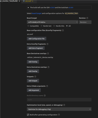
cellular_telemetric_devise.overlay
But I can't see log over Uart to TTL. I have also try using RTT enable and try to view NRF log in RTT viewer but not showing any log. I have try same build and .overlay file in nRF9160 dk Kit in that all things working properly it's redirect log default Uart0 to my custom defined Uart1 pin and i can see log and also RTT log on RTT viwer.
Below are main changes made in different example code in default prj.conf file for RTT Log and Uart Log. I have attached asset_tracker_v2 prj.conf file for your reference
### Logger module
CONFIG_USE_SEGGER_RTT=y
CONFIG_RTT_CONSOLE=y
CONFIG_LOG_BACKEND_RTT=y
CONFIG_LOG=y
CONFIG_LOG_MODE_DEFERRED=y
CONFIG_LOG_BACKEND_UART=n
CONFIG_LOG_SPEED=y
CONFIG_UART_CONSOLE=n
Meanwhile after flashing I showed Uart log which i share below,
In GNSS example :
All pins have been configured as non-secure
[1;34mBooting TF-M v2.1.1-ncs1[0m
[1;34m[Sec Thread] Secure image initializing![0m
TF-M Float ABI: Hard
Lazy stacking enabled
In at_monitor:
All pins have been configured as non-secure
[1;34mBooting TF-M v2.1.1-ncs1[0m
[1;34m[Sec Thread] Secure image initializing
