Need to add driver Max30001 to nrf52dk

Hello team,

We are using nrf52dk with nrf52832 by vs code nrf connect sdk extension.

I have add zephyr led blinky application and flash it on the board and it's working fine.

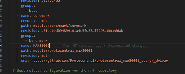
Now I need to add the driver code of Max30001 git hub link

https://github.com/Protocentral/protocentral_max30001_zephyr_driver

Can anyone please help me like how to add this driver code and get the ecg value by SPI

Note: I am new on this zephyr OS, so please if possible guide me step by step solution if possible. It will be very helpful.

  • Hello,

    I have not tested this sensor, but I got it building, so perhaps you can test it. 

    Following the guide you linked to, I added the west.yml snippet to the west.yml file found in NCS\nrf\west.yml, then I opened a cmd terminal, and called "west update", so that it will download the MAX30001 driver to the correct location. NB: You only add from the line starting with "- name: MAX30001", so it looks something like this:

    Then, in whatever application project you are using, add the following to your prj.conf (NB: There is a typo in the guide. It should be "CONFIG_SENSOR_MAX30001=y", not "CONFIG_MAX30001=y".

    CONFIG_GPIO=y
    CONFIG_SENSOR=y
    CONFIG_SENSOR_MAX30001=y
    CONFIG_SOC_NRF52832_ALLOW_SPIM_DESPITE_PAN_58=y
    
    # Log module
    CONFIG_LOG=y
    CONFIG_LOG_BACKEND_UART=y

    Then, if your application folder doesn't have a file called "nrf52dk_nrf52832.overlay", then create it, and in there, write:

    &spi2 {
    	compatible = "nordic,nrf-spim";
    	status = "okay";
    
    	pinctrl-0 = <&spi2_default>;
    	pinctrl-1 = <&spi2_sleep>;
    	pinctrl-names = "default", "sleep";
    	cs-gpios = <&gpio0 22 GPIO_ACTIVE_LOW>;
    
        max30001: max30001@0 {
    		compatible = "maxim,max30001";
    		status = "okay";
    		reg = <0x0>;
    		spi-max-frequency = <DT_FREQ_M(1)>;
    		intb-gpios = <&gpio0 12 GPIO_ACTIVE_LOW>;
    		rtor-enabled;
    		ecg-enabled;
    		bioz-enabled;
    		ecg-gain = <3>;
    		ecg-invert;
    	};
    };

    And do a pristine build (only needed this time, for the compiler to detect the new nrf52dk_nrf52832.overlay file):

    Note that you will get a build error mentioning CONFIG_SOC_NRF52832_ALLOW_SPIM_DESPITE_PAN_58, so add:

    CONFIG_SOC_NRF52832_ALLOW_SPIM_DESPITE_PAN_58=y

    to your prj.conf, and build again.

    If you want to change the default pins used for spi2, just add this on top of your nrf52dk_nrf52832.overlay file:

    &pinctrl {
    	spi2_default: spi2_default {
    		group1 {
    			psels = <NRF_PSEL(SPIM_SCK, 0, 25)>,
    				<NRF_PSEL(SPIM_MOSI, 0, 23)>,
    				<NRF_PSEL(SPIM_MISO, 0, 24)>;
    		};
    	};
    
    	spi2_sleep: spi2_sleep {
    		group1 {
    			psels = <NRF_PSEL(SPIM_SCK, 0, 25)>,
    				<NRF_PSEL(SPIM_MOSI, 0, 23)>,
    				<NRF_PSEL(SPIM_MISO, 0, 24)>;
    			low-power-enable;
    		};
    	};
    
    };

    and change the pin numbers to the ones that you want to use. If it is a shield, you may need to look up which ones that are used on the shield. Note that I changed the spi3 to spi2 in the overlay, because the nRF52832 only has spi0, spi1 and spi2.

    As for the actual application, this is what is a bit difficult for me to test. In your main.c, you need to include these two:

    #include <zephyr/devicetree.h>
    #include <zephyr/drivers/sensor.h>
    #include "max30001.h"
    #include <zephyr/logging/log.h>

    Then something like this may work (but I am unable to test it):

    /*
     * Copyright (c) 2016 Intel Corporation
     *
     * SPDX-License-Identifier: Apache-2.0
     */
    
    #include <stdio.h>
    #include <zephyr/kernel.h>
    #include <zephyr/drivers/gpio.h>
    #include <zephyr/devicetree.h>
    #include <zephyr/drivers/sensor.h>
    #include "max30001.h"
    #include <zephyr/logging/log.h>
    
    #define LOG_MODULE_NAME app
    LOG_MODULE_REGISTER(LOG_MODULE_NAME);
    
    /* 1000 msec = 1 sec */
    #define SLEEP_TIME_MS   2000
    
    /* The devicetree node identifier for the "led0" alias. */
    #define LED0_NODE DT_ALIAS(led0)
    
    /*
     * A build error on this line means your board is unsupported.
     * See the sample documentation for information on how to fix this.
     */
    static const struct gpio_dt_spec led = GPIO_DT_SPEC_GET(LED0_NODE, gpios);
    
    #define SENSOR_DEVICE_NAME max30001
    
    #define THREAD_STACKSIZE        1024
    #define THREAD_PRIORITY         7
    
    K_THREAD_STACK_DEFINE(sensor_thread_stack, THREAD_STACKSIZE);
    static struct k_thread sensor_thread;
    K_MUTEX_DEFINE(sensor_mutex);
    static int32_t sensor_value;
    
    static void thread_entry(void *p1, void *p2, void *p3)
    {
    	int ret;
    	struct sensor_value my_sensor_value;
    
    	const struct device *dev = (const struct device *)p1;
    	struct k_mutex *temp_mutex = (struct k_mutex *)p2;
    	int32_t *temp = (int32_t *)p3;
    
    	while (1) {
            LOG_INF("starting...");
    		ret = sensor_sample_fetch(dev);
    		if (ret != 0) {
    			LOG_INF("sensor_sample_fetch failed ret %d\n", ret);
    			return;
    		}
    
    		ret = sensor_channel_get(dev, SENSOR_CHAN_ECG_UV, &my_sensor_value);    // Look up what this channel does in "max30001.c"
    		if (ret != 0) {
    			LOG_INF("sensor_channel_get failed ret %d\n", ret);
    			return;
    		}
    		if (k_mutex_lock(temp_mutex, K_MSEC(2000)) == 0) {
    			*temp = my_sensor_value.val1;
    			k_mutex_unlock(temp_mutex);
    		} else {
    			LOG_INF("Unable to lock mutex\n");
    		}
            LOG_INF("sleeping...");
    		k_sleep(K_MSEC(2000));
    	}
    }
    
    void sensor_init(void)
    {
        const struct device *dev = DEVICE_DT_GET_ANY(SENSOR_DEVICE_NAME);
        
        __ASSERT(dev != NULL, "Failed to get device binding");
    	__ASSERT(device_is_ready(dev), "Device %s is not ready", dev->name);
    	printk("device is %p, name is %s\n", dev, dev->name);
    	
        k_thread_create(&sensor_thread, sensor_thread_stack,
    			K_THREAD_STACK_SIZEOF(sensor_thread_stack),
    			thread_entry, (void *)dev, (void *)&sensor_mutex, (void*)&sensor_value,
    			THREAD_PRIORITY, 0, K_FOREVER);
    	k_thread_start(&sensor_thread);
    }
    
    int32_t value_get(void)
    {
    	int32_t val = 0;
    
    	if (k_mutex_lock(&sensor_mutex, K_MSEC(100)) == 0) {
    		val = sensor_value;
    		k_mutex_unlock(&sensor_mutex);
    	}
    
    	return val;
    }
    
    int main(void)
    {
    	int ret;
    	bool led_state = true;
        int32_t sensor_value;
        sensor_init();
    
    	if (!gpio_is_ready_dt(&led)) {
    		return 0;
    	}
    
    	ret = gpio_pin_configure_dt(&led, GPIO_OUTPUT_ACTIVE);
    	if (ret < 0) {
    		return 0;
    	}
    
    	while (1) {
            sensor_value = value_get();
            LOG_INF("value = %d", sensor_value);
    
    		ret = gpio_pin_toggle_dt(&led);
    		if (ret < 0) {
    			return 0;
    		}
    
    		led_state = !led_state;
    		LOG_INF("LED state: %s\n", led_state ? "ON" : "OFF");
    		k_msleep(SLEEP_TIME_MS);
    	}
    	return 0;
    }
    

    Attaching the whole application, in case I missed something along the way. As you can see throughout, I added logging using the log module as well. 

    Best regards,

    Edvin

  • Sorry for late reply, 
    Thanks for the help. This gave me better idea and i have successfully integrate the driver.

Related