Hello, I just had a look at the Thingy:91 X with the nRF9151 and nRF5340 SoC's including nRF7002 Wifi support.
My understanding is that the nRF5340 is the main MCU running the main application, while the nRF9151 is used as a Cellular modem
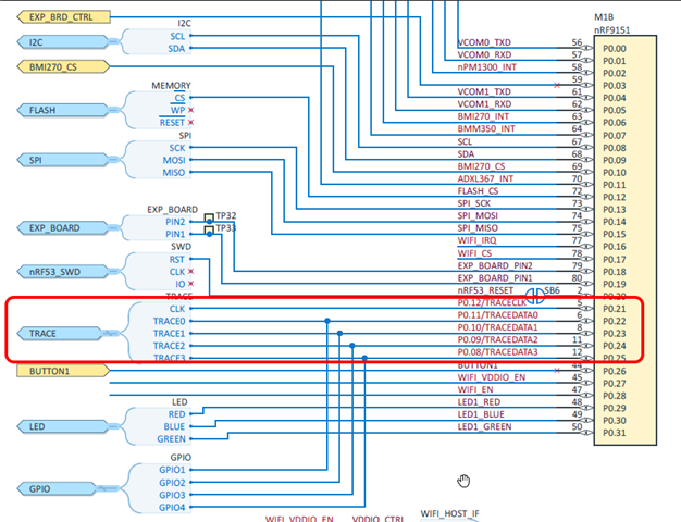
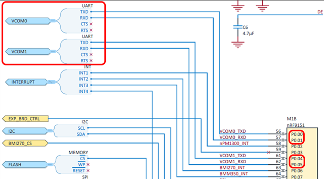
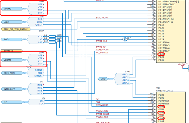
(1) How is communication implemented between the nRF5340 and nRF9151? I noticed that the schematic defines two UART connections between the SoC's, VCOM0 and VCOM1. Are full Cellular modem features on the nRF5340 available through these communication channels? Further, are both channels needed or can one channel be used for a project-specific communication protocol?
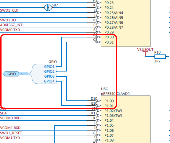
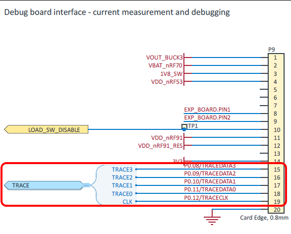
(2) Is my assumption correct that even when using the Thingy:91 X with full features (Cellular, Wifi and Bluetooth active), the nRF5340's "GPIO" pins connected to P9 and the nRF9151's "TRACE" pins, are fully available for project-specific extensions? E.g. adding a MCP2515 CAN controller? In other words, these four pins are NOT needed for communication between the nRF5340 and the nRF9151?
Best regards,
Michael