I am using 9160 as slave which communicates with nrf5340(master) over UART. with flow control disabled everything works but as soon as I enable the hardware flow control then the nf9160 is not able to send the data to nRF5340.
My configuration:
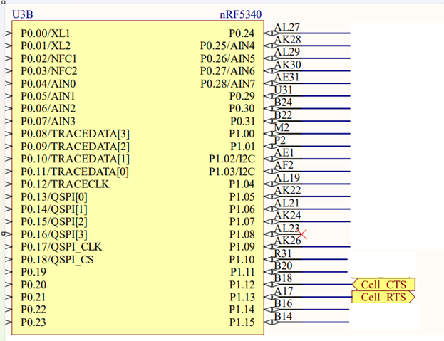
- at 5340 side:
&uart0 {
status = "okay";
current-speed = <460800>;
pinctrl-0 = <&uart0_default>;
pinctrl-1 = <&uart0_sleep>;
pinctrl-names = "default", "sleep";
hw-flow-control;
};
uart0_default: uart0_default {
group1 {
psels = <NRF_PSEL(UART_RTS, 1, 12)>,
<NRF_PSEL(UART_CTS, 1, 13)>;
};
group2 {
psels = <NRF_PSEL(UART_TX, 0, 3)>,
<NRF_PSEL(UART_RX, 0, 5)>;
bias-pull-up;
};
};
uart0_sleep: uart0_sleep {
group1 {
psels = <NRF_PSEL(UART_TX, 0, 3)>,
<NRF_PSEL(UART_RX, 0, 5)>,
<NRF_PSEL(UART_RTS, 1, 12)>,
<NRF_PSEL(UART_CTS, 1, 13)>;
low-power-enable;
};
};
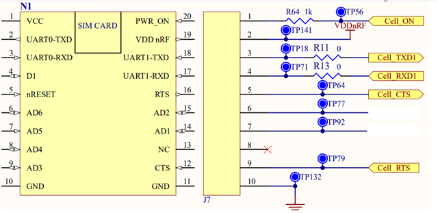
- AT 9160 side:
&uart1 {
status = "okay";
hw-flow-control;
current-speed = <460800>;
pinctrl-0 = <&uart1_default>;
pinctrl-1 = <&uart1_sleep>;
pinctrl-names = "default", "sleep";
};
uart1_default: uart1_default {
group1 {
psels = <NRF_PSEL(UART_TX, 0, 29)>,
<NRF_PSEL(UART_RTS, 0, 27)>,
<NRF_PSEL(UART_CTS, 0, 26)>,
<NRF_PSEL(UART_RX, 0, 28)>;
};
};
uart1_sleep: uart1_sleep {
group1 {
psels = <NRF_PSEL(UART_TX, 0, 29)>,
<NRF_PSEL(UART_RX, 0, 28)>,
<NRF_PSEL(UART_RTS, 0, 27)>,
<NRF_PSEL(UART_CTS, 0, 26)>;
low-power-enable;
};
};
I have also verified in the peripheral that it says flow control is enabled at both the sides