I2C/TWIM doesn't work properly on nRF54H20DK

Hi,

we have nRF54H20DK (SoC rev. "C"). connected to MAX77655 via I2C (SCL ~ P1.0, SDA ~ P1.4 according to I2C restriction).

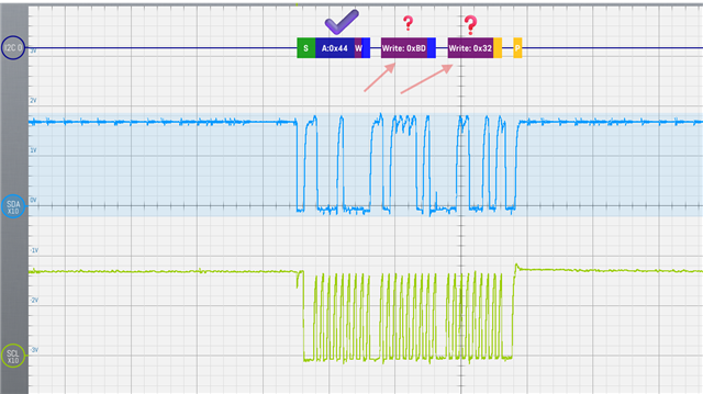
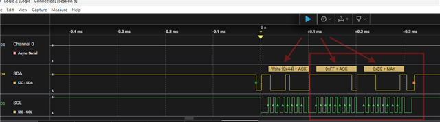
I am trying to test i2c131 for reading/writing data but I can only transfer the first byte (I2C Maxim IC address = 0x44). The other bytes seem to be random and do not depend on the input parameters of the I2C function.

I want to send 3 bytes, but without success.

value "ret" != 0

SDK: v2.9.0-nRF54H20-rc1

IDE: VSCode + nRF Connect plugin

PC: Windows 11 Pro

hardware: nRF54H20DK 

I aware of this note in documentation: "[19] Only SPI master and UART will be supported for the initial limited sampling. " Is this right? Is there any workaround?

Thanks.

code fragment

#define MAX77655_I2C_ADR 0x44

uint8_t i2c_tx_buffer[] = { 4, 7, 1 };

	if(device_is_ready(dev_i2c_ptr)) {
		int config_result = false;
		printk("I2C master device IS ready!\n");
//		 config_result = i2c_configure(dev_i2c_ptr, I2C_SPEED_SET(I2C_SPEED_STANDARD) | I2C_MODE_CONTROLLER );		// I2C_MODE_MASTER
	}
	else {
		printk("I2C master device not ready!\n");
	}


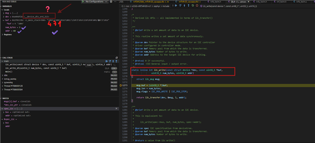
    ret = i2c_write(dev_i2c_ptr, i2c_tx_buffer, sizeof(i2c_tx_buffer), MAX77655_I2C_ADR);

Kconfig

prj.cfg

CONFIG_GPIO=y
CONFIG_I2C=y

Overlay

&i2c131 {
    compatible = "nordic,nrf-twim";
    status = "okay";
    pinctrl-1 = <&i2c131_sleep>;
    pinctrl-0 = <&i2c131_default>;
    pinctrl-names = "default", "sleep";
    clock-frequency = <I2C_BITRATE_STANDARD>;
};

&pinctrl {
    i2c131_default: i2c131_default {
        group1 {
            psels = <NRF_PSEL(TWIM_SCL, 1, 0)>,     // SCK signal must be at pin 0..3 in each port. These pins cannot be used for other SPIS signals.
                    <NRF_PSEL(TWIM_SDA, 1, 4)>;
            bias-pull-up;                           // bias only in this power mode
        };
    };

    i2c131_sleep: i2c131_sleep {
        group1 {
            psels = <NRF_PSEL(TWIM_SCL, 1, 0)>,     // SCK signal must be at pin 0..3 in each port. These pins cannot be used for other SPIS signals.
                    <NRF_PSEL(TWIM_SDA, 1, 4)>;
            low-power-enable;
        };
    };
};

I2C master write issue (sizeof sending data = 3)

Source code:  TWI_USB.ZIP

Parents
  • Hello,

    I have looked at the code snippet.

    Can you try to use i2c_write_dt() instead of using i2c_write() function? It is recommended function for writing I2C devices in newer SDK versions. 

  • Hi,

    thanks for the tip. "i2c_write_dt" is just a wrapper. I reworked my code to a new way and used a new macro (I2C_DT_SPEC_GET) to get the instance. The behavior changed, but it's still not right.

    Structure "spec_i2c" is 32bit aligned (without user determination) &spec_i2c = 0xE09 EF3C.

    	#define I2C131_NODE DT_NODELABEL(max77655_label)
    
    	static const struct i2c_dt_spec spec_i2c = I2C_DT_SPEC_GET(I2C131_NODE);
    	
    	uint8_t i2c_tx_buffer[] = { 4, 7, 1 };
    	
    	if(i2c_is_ready_dt(&spec_i2c)) {
    		printk("I2C master device IS ready!\n");
    		int config_result = i2c_configure(spec_i2c.bus, I2C_SPEED_SET(I2C_SPEED_STANDARD) | I2C_MODE_CONTROLLER );		// I2C_MODE_MASTER
    	}
    	else {
    		printk("I2C master device not ready!\n");
    	}
    	
    	
    	ret = i2c_write_dt(&spec_i2c, i2c_tx_buffer, sizeof(i2c_tx_buffer));
    	if(ret != 0){
    		printk("Failed to write to I2C device address %x\n\r", MAX77655_I2C_ADR);
    	}

    Overlay:
    &i2c131 {
        compatible = "nordic,nrf-twim";
        status = "okay";
        pinctrl-0 = <&i2c131_default>;
        pinctrl-1 = <&i2c131_sleep>;
        pinctrl-names = "default", "sleep";
        // scl-pin = <10>;                          /* Adjust SCL GPIO */
        // sda-pin = <11>;                          /* Adjust SDA GPIO */
        clock-frequency = <I2C_BITRATE_STANDARD>;
    
        max77655_label: max77655@44 {
    //                compatible = "maxim,max77655";
                    compatible = "i2c-device";
                    reg = <0x44>;       // MAX77655 I2C Address 0x44 - Perform all (0x40, 0x44, 0x48, 0x52) reads and writes on the Main Address. 
                                                // The ADDR is a factory one-time programmable (OTP) option. (max77655.pdf page 44 table 7)
                    label = "MAX77655";
        };
    };
    
    &pinctrl {
        i2c131_default: i2c131_default {
            group1 {
                psels = <NRF_PSEL(TWIM_SCL, 1, 0)>,     // SCK signal must be at pin 0..3 in each port. These pins cannot be used for other SPIS signals.
                        <NRF_PSEL(TWIM_SDA, 1, 4)>;
                        bias-pull-up;                   // bias only in this power mode
            };
        };
    
        i2c131_sleep: i2c131_sleep {
            group1 {
                psels = <NRF_PSEL(TWIM_SCL, 1, 0)>,     // SCK signal must be at pin 0..3 in each port. These pins cannot be used for other SPIS signals.
                        <NRF_PSEL(TWIM_SDA, 1, 4)>;
                        low-power-enable;
            };
        };
    };
    Bus signal measured with an oscilloscope:
    I2C master write issue (sizeof sending data = 3)
    This is the debug list for "i2c_write()". All values ​​seem to be fine, but "dev" is "__device_dts_ord_213" - is this ok? We have i2C131.
    Same behavior is on the PORT 0 (SCL ~ P0.03 and SDA ~ P0.05) .
    my project: 4101.TWI_USB.ZIP
Reply
  • Hi,

    thanks for the tip. "i2c_write_dt" is just a wrapper. I reworked my code to a new way and used a new macro (I2C_DT_SPEC_GET) to get the instance. The behavior changed, but it's still not right.

    Structure "spec_i2c" is 32bit aligned (without user determination) &spec_i2c = 0xE09 EF3C.

    	#define I2C131_NODE DT_NODELABEL(max77655_label)
    
    	static const struct i2c_dt_spec spec_i2c = I2C_DT_SPEC_GET(I2C131_NODE);
    	
    	uint8_t i2c_tx_buffer[] = { 4, 7, 1 };
    	
    	if(i2c_is_ready_dt(&spec_i2c)) {
    		printk("I2C master device IS ready!\n");
    		int config_result = i2c_configure(spec_i2c.bus, I2C_SPEED_SET(I2C_SPEED_STANDARD) | I2C_MODE_CONTROLLER );		// I2C_MODE_MASTER
    	}
    	else {
    		printk("I2C master device not ready!\n");
    	}
    	
    	
    	ret = i2c_write_dt(&spec_i2c, i2c_tx_buffer, sizeof(i2c_tx_buffer));
    	if(ret != 0){
    		printk("Failed to write to I2C device address %x\n\r", MAX77655_I2C_ADR);
    	}

    Overlay:
    &i2c131 {
        compatible = "nordic,nrf-twim";
        status = "okay";
        pinctrl-0 = <&i2c131_default>;
        pinctrl-1 = <&i2c131_sleep>;
        pinctrl-names = "default", "sleep";
        // scl-pin = <10>;                          /* Adjust SCL GPIO */
        // sda-pin = <11>;                          /* Adjust SDA GPIO */
        clock-frequency = <I2C_BITRATE_STANDARD>;
    
        max77655_label: max77655@44 {
    //                compatible = "maxim,max77655";
                    compatible = "i2c-device";
                    reg = <0x44>;       // MAX77655 I2C Address 0x44 - Perform all (0x40, 0x44, 0x48, 0x52) reads and writes on the Main Address. 
                                                // The ADDR is a factory one-time programmable (OTP) option. (max77655.pdf page 44 table 7)
                    label = "MAX77655";
        };
    };
    
    &pinctrl {
        i2c131_default: i2c131_default {
            group1 {
                psels = <NRF_PSEL(TWIM_SCL, 1, 0)>,     // SCK signal must be at pin 0..3 in each port. These pins cannot be used for other SPIS signals.
                        <NRF_PSEL(TWIM_SDA, 1, 4)>;
                        bias-pull-up;                   // bias only in this power mode
            };
        };
    
        i2c131_sleep: i2c131_sleep {
            group1 {
                psels = <NRF_PSEL(TWIM_SCL, 1, 0)>,     // SCK signal must be at pin 0..3 in each port. These pins cannot be used for other SPIS signals.
                        <NRF_PSEL(TWIM_SDA, 1, 4)>;
                        low-power-enable;
            };
        };
    };
    Bus signal measured with an oscilloscope:
    I2C master write issue (sizeof sending data = 3)
    This is the debug list for "i2c_write()". All values ​​seem to be fine, but "dev" is "__device_dts_ord_213" - is this ok? We have i2C131.
    Same behavior is on the PORT 0 (SCL ~ P0.03 and SDA ~ P0.05) .
    my project: 4101.TWI_USB.ZIP
Children
No Data
Related