
Hi there!
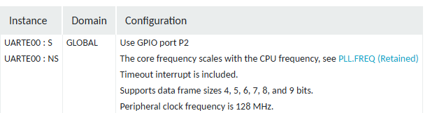
May I know how to have UART00 on P2 like what is shown below as I wanted to have higher speed.
Is it the same as other UART assignments on P0 and P1?
Thanks!
Hi there!
May I know how to have UART00 on P2 like what is shown below as I wanted to have higher speed.
Is it the same as other UART assignments on P0 and P1?
Thanks!
Hello,
Please see the cross power-domain section of the pin assignment documentation for the nRF54L15.
What pins specifically are you trying to use? Have you used a logic analyzer to see if any of the pins are doing anything?
Best regards,
Edvin
Hi there!
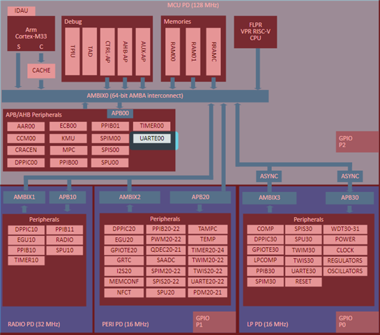
I have read the link you shared before. I know it mentions dedicated pins in pin assignment table but I still want to know if I can use any P2 pins for UARTE00. For example, is it possible to use P2.06 to P2.09 for UART with flow control? I understand UART is not mentioned under description and dedicated function of P2.06 but I wanted to know if I can use it by configuration of certain registers.
Hi there!
I have read the link you shared before. I know it mentions dedicated pins in pin assignment table but I still want to know if I can use any P2 pins for UARTE00. For example, is it possible to use P2.06 to P2.09 for UART with flow control? I understand UART is not mentioned under description and dedicated function of P2.06 but I wanted to know if I can use it by configuration of certain registers.
Yes. My interpretation is that you can:
https://docs.nordicsemi.com/bundle/ps_nrf54L15/page/uarte.html#d1900e814
But I must admit I have not tested it. Do you have an application that you can't get working with UARTE00 on P2? If so, feel free to upload it, so that I can have a look.
Best regards,
Edvin
Hi there!
I have tried to add UARTE21 to P1 and UARTE00 to P2 respectively.
UARTE21 works well but TX of UARTE00 only shows garbled code and RX of UARTE00 is not able to toggle LED of the DK. Could you give me some hints what did I miss?
Here is the sample I follow
Following is the application I have, including main.c, CMakelist, cong and dts I am using.
/*
 * Copyright (c) 2016 Intel Corporation
 *
 * SPDX-License-Identifier: Apache-2.0
 */

/* Controlling LEDs through UART. Press 1-3 on your keyboard to toggle LEDS 1-3 on your development
 * kit */

#include <zephyr/kernel.h>
#include <zephyr/device.h>
#include <zephyr/devicetree.h>
#include <zephyr/drivers/gpio.h>
#include <zephyr/sys/printk.h>
/* STEP 3 - Include the header file of the UART driver in main.c */
#include <zephyr/drivers/uart.h>

/* 1000 msec = 1 sec */
#define SLEEP_TIME_MS 1000

/* STEP 10.1.1 - Define the size of the receive buffer */
#define RECEIVE_BUFF_SIZE 10

/* STEP 10.2 - Define the receiving timeout period */
#define RECEIVE_TIMEOUT 100

/* STEP 5.1 - Get the device pointers of the LEDs through gpio_dt_spec */
/* The nRF7002dk has only 2 LEDs so this step uses a compile-time condition to reflect the DK you
 * are building for */
#if defined(CONFIG_BOARD_NRF7002DK_NRF5340_CPUAPP) || defined(CONFIG_BOARD_NRF7002DK_NRF5340_CPUAPP_NS)
static const struct gpio_dt_spec led0 = GPIO_DT_SPEC_GET(DT_ALIAS(led0), gpios);
static const struct gpio_dt_spec led1 = GPIO_DT_SPEC_GET(DT_ALIAS(led1), gpios);
#else
static const struct gpio_dt_spec led0 = GPIO_DT_SPEC_GET(DT_ALIAS(led0), gpios);
static const struct gpio_dt_spec led1 = GPIO_DT_SPEC_GET(DT_ALIAS(led1), gpios);
static const struct gpio_dt_spec led2 = GPIO_DT_SPEC_GET(DT_ALIAS(led2), gpios);
#endif

/* STEP 4.1 - Get the device pointer of the UART hardware */
#if defined(CONFIG_BOARD_NRF54L15DK_NRF54L15_CPUAPP) || defined(CONFIG_BOARD_NRF54L15DK_NRF54L15_CPUAPP_NS)
//const struct device *uart = DEVICE_DT_GET(DT_NODELABEL(uart20));
const struct device *uart = DEVICE_DT_GET(DT_NODELABEL(uart00));
#else
const struct device *uart = DEVICE_DT_GET(DT_NODELABEL(uart0));
#endif

/* STEP 9.1 - Define the transmission buffer, which is a buffer to hold the data to be sent over
 * UART */
static uint8_t tx_buf[] = {
#if defined(CONFIG_BOARD_NRF7002DK_NRF5340_CPUAPP) || defined(CONFIG_BOARD_NRF7002DK_NRF5340_CPUAPP_NS)
	"nRF Connect SDK Fundamentals Course\r\n"
	"Press 1-2 on your keyboard to toggle LEDS 1-2 on your development kit\r\n"};
#elif defined(CONFIG_BOARD_NRF54L15DK_NRF54L15_CPUAPP) || defined(CONFIG_BOARD_NRF54L15DK_NRF54L15_CPUAPP_NS)
	"nRF Connect SDK Fundamentals Course\r\n"
	"Press 0-2 on your keyboard to toggle LEDS 0-2 on your development kit\r\n"};
#else
	"nRF Connect SDK Fundamentals Course\r\n"
	"Press 1-3 on your keyboard to toggle LEDS 1-3 on your development kit\r\n"};
#endif

/* STEP 10.1.2 - Define the receive buffer */
static uint8_t rx_buf[RECEIVE_BUFF_SIZE] = {0};

/* STEP 7 - Define the callback function for UART */
static void uart_cb(const struct device *dev, struct uart_event *evt, void *user_data)
{
	switch (evt->type) {

	case UART_RX_RDY:
    #if defined(CONFIG_BOARD_NRF7002DK_NRF5340_CPUAPP) || defined(CONFIG_BOARD_NRF7002DK_NRF5340_CPUAPP_NS)
		if ((evt->data.rx.len) == 1) {

			if (evt->data.rx.buf[evt->data.rx.offset] == '1') {
				gpio_pin_toggle_dt(&led0);
			} else if (evt->data.rx.buf[evt->data.rx.offset] == '2') {
				gpio_pin_toggle_dt(&led1);
			}
		}
    #elif defined(CONFIG_BOARD_NRF54L15DK_NRF54L15_CPUAPP) || defined(CONFIG_BOARD_NRF54L15DK_NRF54L15_CPUAPP_NS)
		if ((evt->data.rx.len) == 1) {
			if (evt->data.rx.buf[evt->data.rx.offset] == '0') {
				gpio_pin_toggle_dt(&led0);
			} else if (evt->data.rx.buf[evt->data.rx.offset] == '1') {
				gpio_pin_toggle_dt(&led1);
			} else if (evt->data.rx.buf[evt->data.rx.offset] == '2') {
				gpio_pin_toggle_dt(&led2);
			}
        }
    #else
		if ((evt->data.rx.len) == 1) {

			if (evt->data.rx.buf[evt->data.rx.offset] == '1') {
				gpio_pin_toggle_dt(&led0);
			} else if (evt->data.rx.buf[evt->data.rx.offset] == '2') {
				gpio_pin_toggle_dt(&led1);
			} else if (evt->data.rx.buf[evt->data.rx.offset] == '3') {
				gpio_pin_toggle_dt(&led2);
			}
		}
#endif
		break;
	case UART_RX_DISABLED:
		uart_rx_enable(dev, rx_buf, sizeof rx_buf, RECEIVE_TIMEOUT);
		break;

	default:
		break;
	}
}

int main(void)
{
	int ret;

	/* STEP 4.2 - Verify that the UART device is ready */
	if (!device_is_ready(uart)) {
		printk("UART device not ready\n");
		return 1;
	}
	/* STEP 5.2 - Verify that the LED devices are ready */
	if (!device_is_ready(led0.port)) {
		printk("GPIO device is not ready\n");
		return 1;
	}
/* STEP 6 - Configure the GPIOs of the LEDs */
#if defined(CONFIG_BOARD_NRF7002DK_NRF5340_CPUAPP) ||                                              \
	defined(CONFIG_BOARD_NRF7002DK_NRF5340_CPUAPP_NS)
	ret = gpio_pin_configure_dt(&led0, GPIO_OUTPUT_ACTIVE);
	if (ret < 0) {
		return 1;
	}
	ret = gpio_pin_configure_dt(&led1, GPIO_OUTPUT_ACTIVE);
	if (ret < 0) {
		return 1;
	}
#else
	ret = gpio_pin_configure_dt(&led0, GPIO_OUTPUT_ACTIVE);
	if (ret < 0) {
		return 1;
	}
	ret = gpio_pin_configure_dt(&led1, GPIO_OUTPUT_ACTIVE);
	if (ret < 0) {
		return 1;
	}
	ret = gpio_pin_configure_dt(&led2, GPIO_OUTPUT_ACTIVE);
	if (ret < 0) {
		return 1;
	}
#endif

	/* STEP 8 - Register the UART callback function */
	ret = uart_callback_set(uart, uart_cb, NULL);
	if (ret) {
		return 1;
	}
	/* STEP 9.2 - Send the data over UART by calling uart_tx() */
	ret = uart_tx(uart, tx_buf, sizeof(tx_buf), SYS_FOREVER_MS);
	if (ret) {
		return 1;
	}
	/* STEP 10.3  - Start receiving by calling uart_rx_enable() and pass it the address of the
	 * receive  buffer */
	ret = uart_rx_enable(uart, rx_buf, sizeof rx_buf, RECEIVE_TIMEOUT);
	if (ret) {
		return 1;
	}
	while (1) {
		k_msleep(SLEEP_TIME_MS);
	}
}
#
# Copyright (c) 2016 Intel Corporation
#
# SPDX-License-Identifier: Apache-2.0
#

cmake_minimum_required(VERSION 3.20.0)
find_package(Zephyr REQUIRED HINTS $ENV{ZEPHYR_BASE})
project(UART)

target_sources(app PRIVATE src/main.c)
Hi again,
I just changed the baud rate to 921600 in my serial port tool, then Tx of UARTE00 becomes readable text but it should be 115200 according to device tree I attached above . For Rx, it still cannot control LED of DK until I change it to P2.07 with baud rate 921600. Do you know why the actual baud rate is different from my setting and why Rx as P2.06 is not working but P2.07? Look forward to hearing from you. Thanks!
I have the same experience.
for uart00, it works only with the dedicated pin function. not able to use P2.06 for rx. try changing to P2.07.
also observed that the baud rate on the terminal program must be 8x of the uart current-speed.
not sure if has anything to do with the peripheral clock frequency being 128 MHz in mcu domain?
jing
Hello,
Can any of you please upload the application that you are using to reproduce this. It is easier, and quicker, for me to reproduce, and potentially forward to our developers if I have something that I can just build and flash.
Best regards,
Edvin

