HI
.
It was configured to detect low voltage of the battery using lpcomp.
This configuration is already being used in mass production of other products and there have been no major problems.
.
However, during this new development, a phenomenon occurred where the reference voltage setting of lpcomp did not match the calculation.
(Circuit and SW configuration are the same as those currently in mass production)
.
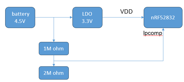
1. circuit configuration
- Internal LDO output and nRF52832 VDD: 3.3V
-Battery voltage range: 4.5V~3.0V
- Low voltage detection voltage: 3.3V
.
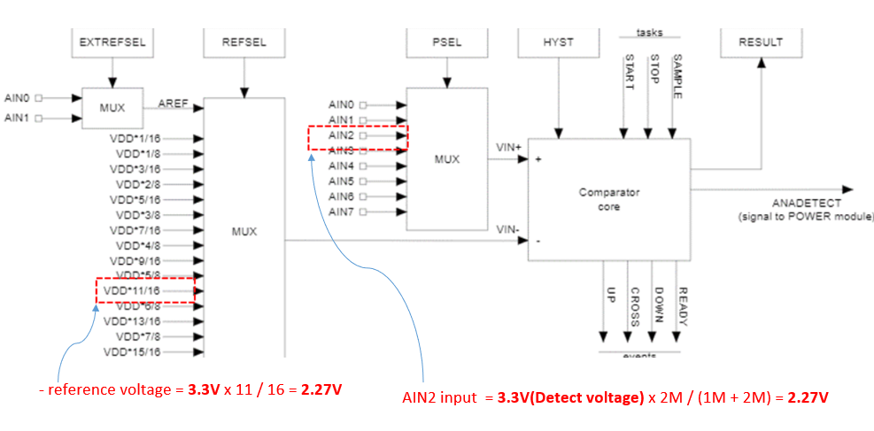
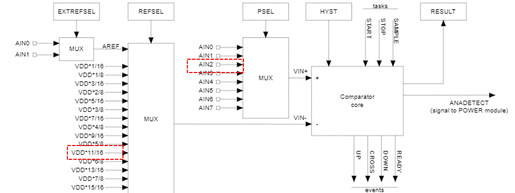
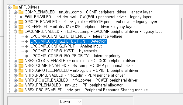
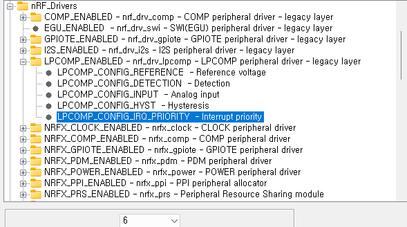
2. lpcom configuration
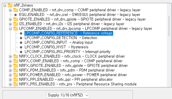
- reference voltage = 3.3V x 11 / 16 = 2.27V
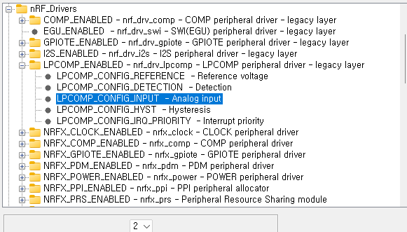
- AIN5 input = 3.3V x 2M / (1M + 2M) = 2.27V
.
.
.
.
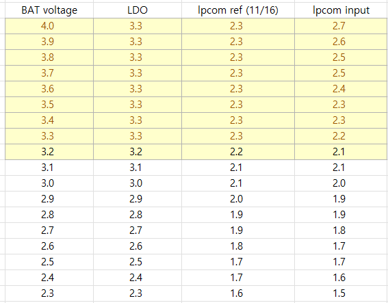
3. Problem occurred
- The reference voltage of lpcomp is 11/16 according to the above calculation.
However, if it actually operates at 11/16, it does not detect 3.3V and detects around 2.9V.
.
So, I adjusted the reference voltage to 15/16 and it was detected at 3.3V normally.
.
- If you measure the input voltage of lpcomp, it is normal.
.