nPM1300 Enabling of LDO causes Vsys to drop

Hello everyone,

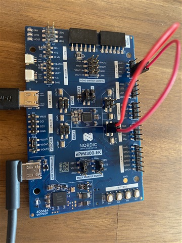
we have an in-house HW with the nPM1300. Both load switches are configured as LDOs as described in datasheet chapter 9.3 configuration 1.

LDO1 is used to provide power for an RGB with about 2 mA for each color. At the output of LDO1 are two 10 µF capacitors as recommended.

The RGB is controlled with MOSFETs from a nRF52840 SoC.

When the MOSFETs block current flow through the RGB so there is no load, everything looks good.

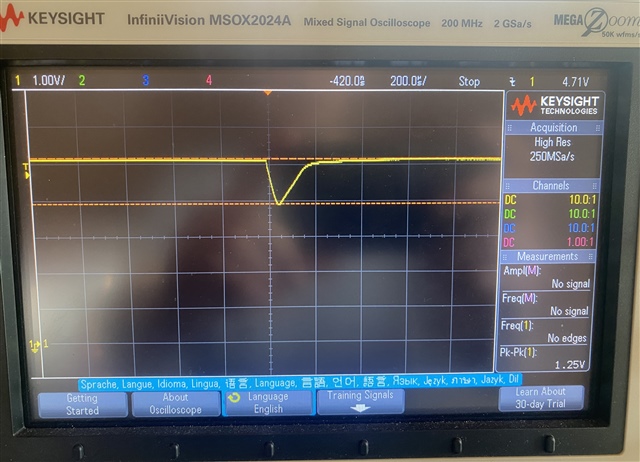
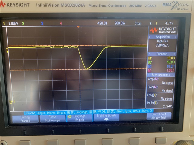
If I enable the MOSFETs before the LDO is enabled I see a voltage drop of around 1.6 V at VSys for about 300 ms.

Voltage Drop at Vsys with RGB at output

Is it expected behaviour that Vsys can drop by 1.6 V when LDO1 is enabled with a consumer like a RGB (~in total 6 mA)?

Considering the activation of both LDOs at once with consumers drawing even more current than 6 mA during startup seems like it could cause a reset of the nRF52840 SoC?
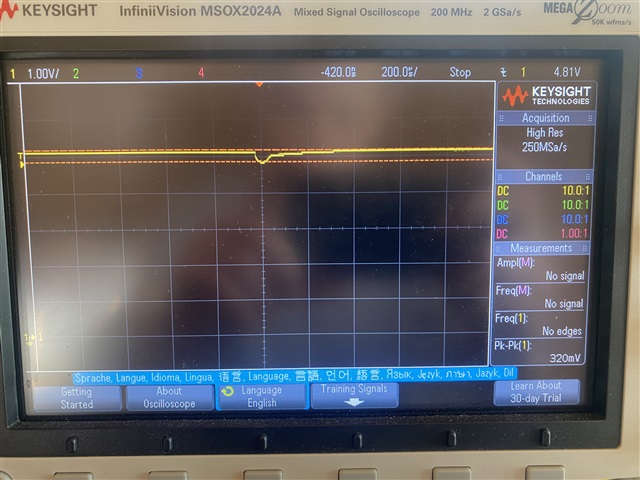
Vbus current limit

I also increased the Vbus current limit from the default value of 100 mA to 500 mA, which decreased the voltage drop at Vsys. If voltage fluctuations are not acceptable, do I have to ensure Vbus is configured accoordingly? As the LDO can deliver only up to 50 mA I was not expecting to see such dramatic voltage drops at Vsys with only a single RGB even if the vbus current limit is set to 100 mA. The nRF52840 SoC has no BLE running and consumes around 15 mA when the debugger is attached.

Other regulators

Is it possible to see similiar effects with the buck regulators? In the above tests the buck regulators were off. I can currently not test their behaviour myself.

Thanks!
Markus

Parents
  • Hello,

    in the meantime I have been conducting some more measurements. I have ordered a brand new nPM1300 EK and did the following tests purely with the PowerUp in its latest version 1.3.1. Before I continue testing on my custome HW I want to verify my results with you first.

    I connected the EK as recommended to my laptop, the PowerUp app was able to connect to the on board SoC and control the PMIC. I have configured the board for LDO usage. See picture below. The input voltage for both LDOs is sourced from Vsys.


    The below measurements were done with an oscilloscope. There was no battery connected.

    The images from the osci are showing Vsys.


    1 - Switch to mode LDO with Vbus curr limit 100 mA

    • Vbus current limit: 100 mA
    • Discharge Resistor LDO1: disabled
    • Discharge Resistor LDO2: disabled
    • LDO1 Output voltage: 1 V
    • LDO2 Output voltage: 1 V

    As soon as I switch to mode LDO for both LDO1 (/LDO2) I get the following:

    Side-note: the PowerUp app indicates the LDO is disabled when switching to mode LDO, but LDO is automatically turned on.

    2 - Switch to mode LDO with Vbus curr limit 500 mA

    • Vbus current limit: 500 mA
    • Discharge Resistor LDO1: disabled
    • Discharge Resistor LDO2: disabled
    • LDO1 Output voltage: 1 V
    • LDO2 Output voltage: 1 V

    There was not voltage drop detected. At "5 - " I noticed that the voltage drop was not happening on every enable of LDO. So it is possible with the ~4 tests I ran I just did not run into it.

    3 - Enable LDO without discharge resistor and Vbus curr limit 100 mA / 500 mA

    • Vbus current limit: 100 / 500 mA
    • Discharge Resistor LDO1: disabled
    • Discharge Resistor LDO2: disabled
    • LDO1 Output voltage: 1 V / 3.3 V
    • LDO2 Output voltage: 1 V / 3.3 V

    In this case all is good and I can not detect a drop at Vsys. If there is one it is < 300 mV.

    4 - Enable LDO with discharge resistor and Vbus curr limit 100 mA

    • Vbus current limit: 100 mA
    • Discharge Resistor LDO1: enabled
    • Discharge Resistor LDO2: enabled
    • LDO1 Output voltage: 1 V
    • LDO2 Output voltage: 1 V

    If I enable any of the two LDOs with its discharge resistor still enabled I get the following:

    5 - Enable LDO with discharge resistor and Vbus curr limit 500 mA

    • Vbus current limit: 500 mA
    • Discharge Resistor LDO1: enabled
    • Discharge Resistor LDO2: enabled
    • LDO1 Output voltage: 1 V
    • LDO2 Output voltage: 1 V

    If I enable any of the two LDOs with its discharge resistor still enabled I get the following:

    6 - Enable LDO with discharge resistor and increased output voltage and Vbus curr limit at 100 mA

    • Vbus current limit: 100 mA
    • Discharge Resistor LDO1: enabled
    • Discharge Resistor LDO2: enabled
    • LDO1 Output voltage: 3.3 V
    • LDO2 Output voltage: 3.3 V

    If I enable any of the two LDOs with its discharge resistor still enabled I get the following:

    --> voltage drop almost doubles to 2 V.

    7 - Supply LDO In from Buck1 with 1.8 and 3.3 V

    • Vbus current limit: 100 mA
    • Discharge Resistor LDO1: disabled
    • Discharge Resistor LDO2: disabled
    • LDO1 Output voltage: 3.3 V
    • LDO2 Output voltage: 3.3 V

    When I switch to mode LDO there is no drop at Vsys with 1.8 V from Buck1 and if Buck1 provides 3.3 V there is a drop at Vsys around 500 mV. I have no images for these two.

    Conclusion

    • when switching to mode LDO on PowerUp app Vsys drops
      • drop ~ 1 V for 100 mA current limit Vbus
      • drop ~ 300 mV for 500 mA current limit Vbus
      • when increased to 1.5 A I did not detect a voltage drop
    • when enabling the LDO while discharge resistor is enabled, Vsys drops
      • drop is higher when input voltage of LDO is higher
      • drop is higher when output voltage of LDO is higher

    I imagine that if my hardware draws some more current from Vsys than the EK, the drops are likely to be even higher.

    Can you verify that this is how the nPM1300 is expected to behave? If no, I used a brand new nPM1300 EK and a minimal setup, any suggestions of root cause?

    Thanks!
    Markus

Reply
  • Hello,

    in the meantime I have been conducting some more measurements. I have ordered a brand new nPM1300 EK and did the following tests purely with the PowerUp in its latest version 1.3.1. Before I continue testing on my custome HW I want to verify my results with you first.

    I connected the EK as recommended to my laptop, the PowerUp app was able to connect to the on board SoC and control the PMIC. I have configured the board for LDO usage. See picture below. The input voltage for both LDOs is sourced from Vsys.


    The below measurements were done with an oscilloscope. There was no battery connected.

    The images from the osci are showing Vsys.


    1 - Switch to mode LDO with Vbus curr limit 100 mA

    • Vbus current limit: 100 mA
    • Discharge Resistor LDO1: disabled
    • Discharge Resistor LDO2: disabled
    • LDO1 Output voltage: 1 V
    • LDO2 Output voltage: 1 V

    As soon as I switch to mode LDO for both LDO1 (/LDO2) I get the following:

    Side-note: the PowerUp app indicates the LDO is disabled when switching to mode LDO, but LDO is automatically turned on.

    2 - Switch to mode LDO with Vbus curr limit 500 mA

    • Vbus current limit: 500 mA
    • Discharge Resistor LDO1: disabled
    • Discharge Resistor LDO2: disabled
    • LDO1 Output voltage: 1 V
    • LDO2 Output voltage: 1 V

    There was not voltage drop detected. At "5 - " I noticed that the voltage drop was not happening on every enable of LDO. So it is possible with the ~4 tests I ran I just did not run into it.

    3 - Enable LDO without discharge resistor and Vbus curr limit 100 mA / 500 mA

    • Vbus current limit: 100 / 500 mA
    • Discharge Resistor LDO1: disabled
    • Discharge Resistor LDO2: disabled
    • LDO1 Output voltage: 1 V / 3.3 V
    • LDO2 Output voltage: 1 V / 3.3 V

    In this case all is good and I can not detect a drop at Vsys. If there is one it is < 300 mV.

    4 - Enable LDO with discharge resistor and Vbus curr limit 100 mA

    • Vbus current limit: 100 mA
    • Discharge Resistor LDO1: enabled
    • Discharge Resistor LDO2: enabled
    • LDO1 Output voltage: 1 V
    • LDO2 Output voltage: 1 V

    If I enable any of the two LDOs with its discharge resistor still enabled I get the following:

    5 - Enable LDO with discharge resistor and Vbus curr limit 500 mA

    • Vbus current limit: 500 mA
    • Discharge Resistor LDO1: enabled
    • Discharge Resistor LDO2: enabled
    • LDO1 Output voltage: 1 V
    • LDO2 Output voltage: 1 V

    If I enable any of the two LDOs with its discharge resistor still enabled I get the following:

    6 - Enable LDO with discharge resistor and increased output voltage and Vbus curr limit at 100 mA

    • Vbus current limit: 100 mA
    • Discharge Resistor LDO1: enabled
    • Discharge Resistor LDO2: enabled
    • LDO1 Output voltage: 3.3 V
    • LDO2 Output voltage: 3.3 V

    If I enable any of the two LDOs with its discharge resistor still enabled I get the following:

    --> voltage drop almost doubles to 2 V.

    7 - Supply LDO In from Buck1 with 1.8 and 3.3 V

    • Vbus current limit: 100 mA
    • Discharge Resistor LDO1: disabled
    • Discharge Resistor LDO2: disabled
    • LDO1 Output voltage: 3.3 V
    • LDO2 Output voltage: 3.3 V

    When I switch to mode LDO there is no drop at Vsys with 1.8 V from Buck1 and if Buck1 provides 3.3 V there is a drop at Vsys around 500 mV. I have no images for these two.

    Conclusion

    • when switching to mode LDO on PowerUp app Vsys drops
      • drop ~ 1 V for 100 mA current limit Vbus
      • drop ~ 300 mV for 500 mA current limit Vbus
      • when increased to 1.5 A I did not detect a voltage drop
    • when enabling the LDO while discharge resistor is enabled, Vsys drops
      • drop is higher when input voltage of LDO is higher
      • drop is higher when output voltage of LDO is higher

    I imagine that if my hardware draws some more current from Vsys than the EK, the drops are likely to be even higher.

    Can you verify that this is how the nPM1300 is expected to behave? If no, I used a brand new nPM1300 EK and a minimal setup, any suggestions of root cause?

    Thanks!
    Markus

Children
No Data
Related