
Hello,
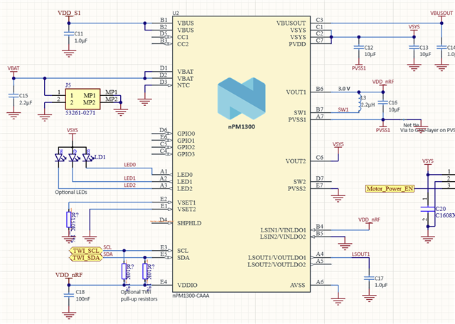
I am using the nPM1300 IC on a custom PCB with the nRF5340 + nRF7002 + nPM1300 configuration. sdk v2.8.0
I am trying to read the battery status (ADC value) via TWI, but I am unable to retrieve the battery information.
I have a few questions:
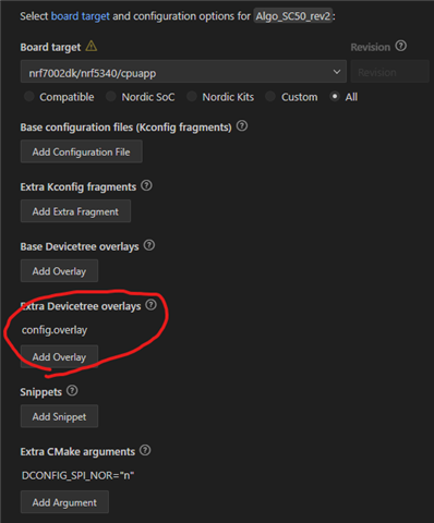
- When using the nPM1300, is it necessary to export the configuration from the nPM PowerUP app as an overlay and include it in the project during development?
- If so, where should this overlay be placed in VS Code? (Is the part shown in the image correct?)
- Can you check if there are any issues with my DTS and code?
nrf7002dk_nrf5340_cpuapp.dts
/*
 * Copyright (c) 2024 Nordic Semiconductor ASA
 *
 * SPDX-License-Identifier: Apache-2.0
 */

/dts-v1/;
#include <nordic/nrf5340_cpuapp_qkaa.dtsi>
#include "nrf5340_cpuapp_common.dtsi"
#include "nrf7002dk_nrf5340_cpuapp_pinctrl.dtsi"

/ {
	model = "Nordic NRF7002 DK NRF5340 Application";
	compatible = "nordic,nrf7002-dk-nrf5340-cpuapp";

	chosen {
		zephyr,sram = &sram0_image;
		zephyr,flash = &flash0;
		zephyr,code-partition = &slot0_partition;
		zephyr,sram-secure-partition = &sram0_s;
		zephyr,sram-non-secure-partition = &sram0_ns;
		zephyr,wifi = &wlan0;
	};

	zephyr,user {
		io-channels = <&adc 0>;

		DT1-gpios = <&gpio1 11 0>;
		DT2-gpios = <&gpio1 13 0>;
		DT3-gpios = <&gpio0 7 0>;
		DT4-gpios = <&gpio0 25 0>;

		BAT_EN-gpios = <&gpio0 6 0>;

		// MOTOR_PWM-gpios = <&gpio0 2 0>;
		pwms = <&pwm0 0 20 PWM_POLARITY_NORMAL>;
	};
};

&pinctrl {
	pwm0_default: pwm0_default {
		group1 {
			psels = <NRF_PSEL(PWM_OUT0, 1, 2)>;
			// nordic,invert;
		};
	};

	pwm0_sleep: pwm0_sleep {
		group1 {
			psels = <NRF_PSEL(PWM_OUT0, 1, 2)>;
			low-power-enable;
		};
	};

	spi0_default: spi0_default {
		group1 {
			psels = <NRF_PSEL(SPIM_SCK, 0, 20)>,        /* SPI SCK 핀 */
					<NRF_PSEL(SPIM_MOSI, 0, 21)>,       /* SPI MOSI 핀 */
					<NRF_PSEL(SPIM_MISO, 0, 22)>;       /* SPI MISO 핀 */
		};
	};

	spi0_sleep: spi0_sleep {
		group1 {
				psels = <NRF_PSEL(SPIM_SCK, 0, 20)>,        /* SPI SCK 핀 */
						<NRF_PSEL(SPIM_MOSI, 0, 21)>,       /* SPI MOSI 핀 */
						<NRF_PSEL(SPIM_MISO, 0, 22)>;       /* SPI MISO 핀 */
				low-power-enable;
		};
	};

	i2c1_default: i2c1_default {
        group1 {
            psels = <NRF_PSEL(TWIM_SCL, 1, 6)>,
                    <NRF_PSEL(TWIM_SDA, 1, 4)>;
        };
    };

    i2c1_sleep: i2c1_sleep {
        group1 {
            psels = <NRF_PSEL(TWIM_SCL, 1, 6)>,
                    <NRF_PSEL(TWIM_SDA, 1, 4)>;
            low-power-enable;
        };
    };
};


&qspi {
	nrf70: nrf7002@1 {
		compatible = "nordic,nrf7002-qspi";
		status = "okay";
		reg = <1>;
		qspi-frequency = <24000000>;
		qspi-quad-mode;

		#include "nrf70_common.dtsi"
		#include "nrf70_common_5g.dtsi"
	};
};

&adc {
	#address-cells = <1>;
	#size-cells = <0>;
	status = "okay";

	channel@0 {
		reg = <0>;
		zephyr,gain = "ADC_GAIN_1_2";
		zephyr,reference = "ADC_REF_VDD_1_4";
		zephyr,acquisition-time = <0>;
		zephyr,resolution = <14>;
		zephyr,input-positive = <NRF_SAADC_AIN0>;
	};
	channel@1 {
		reg = <1>;
		zephyr,gain = "ADC_GAIN_1_6";
		zephyr,reference = "ADC_REF_VDD_1_4";
		zephyr,acquisition-time = <0>;
		zephyr,resolution = <12>;
		zephyr,input-positive = <NRF_SAADC_AIN1>;
	};
 };

&spi0 {
	compatible = "nordic,nrf-spim";
    status = "okay";

	pinctrl-0 = <&spi0_default>;
	pinctrl-1 = <&spi0_sleep>;
	pinctrl-names = "default", "sleep";

	label = "SPI_0";

    cs-gpios = <&gpio0 8 GPIO_ACTIVE_HIGH>,  /* CS1 핀 */
               <&gpio0 9 GPIO_ACTIVE_HIGH>,  /* CS2 핀 */
               <&gpio0 10 GPIO_ACTIVE_HIGH>;  /* CS3 핀 */

    slave1: spi-dev1@0 {
        compatible = "spi-device";
        reg = <0>;       /* 슬레이브 1의 ID */
        spi-max-frequency = <8000000>;
        // cs-gpios = <&gpio0 8 GPIO_ACTIVE_LOW>;
    };

    slave2: spi-dev2@1 {
        compatible = "spi-device";
        reg = <1>;       /* 슬레이브 2의 ID */
        spi-max-frequency = <8000000>;
        // cs-gpios = <&gpio0 9 GPIO_ACTIVE_LOW>;
    };

    slave3: spi-dev3@2 {
        compatible = "spi-device";
        reg = <2>;       /* 슬레이브 3의 ID */
        spi-max-frequency = <8000000>;
        // cs-gpios = <&gpio0 10 GPIO_ACTIVE_LOW>;
    };
};

&pwm0 {
    status = "okay";                      /* PWM 컨트롤러 활성화 */
    pinctrl-0 = <&pwm0_default>;          /* 기본 설정 */
	pinctrl-1 = <&pwm0_sleep>;
    pinctrl-names = "default", "sleep";
	// label = "PWM_0";
};

// Disable
&uart0 {
    status = "disabled";
};

&gpio_fwd {
    status = "disabled";

	uart {
        status = "disabled";
    };
};

// &spi4 {
//     status = "disabled";
// };

// &mx25r64 {
//     status = "disabled";
// };

&spi4 {
    status = "disabled";

	mx25r64: mx25r6435f@0 {
		status = "disabled";
	};
};

&i2c1 {
    status = "okay";
	compatible = "nordic,nrf-twim";  // I2C 마스터 모드 사용
    clock-frequency = <I2C_BITRATE_FAST>; // 400kHz 설정 (400kHz)

    pinctrl-0 = <&i2c1_default>;
    pinctrl-1 = <&i2c1_sleep>;
    pinctrl-names = "default", "sleep";

    nPM1300: pmic@6b {
        compatible = "nordic,npm1300";
        reg = <0x6B>;  // nPM1300의 I2C 주소
        status = "okay";
    };
};

&led0 {
	gpios = <&gpio1 12 0>;
};

/* Flash Memory에 새로운 영역 추가 */
&flash0 {
    partitions {
        compatible = "fixed-partitions";

        /* 새로운 Flash 영역 추가 */
        custom_flash_storage: partition@100000 {
            label = "custom_storage";  // ✅ 기존 storage와 구분하기 위해 이름 변경
            reg = <0x100000 0x20000>;  /* 128 KB (0x100000 ~ 0x120000) */
        };
    };
};
- main.c
#include <zephyr/logging/log.h>
LOG_MODULE_REGISTER(Provisioning, CONFIG_LOG_DEFAULT_LEVEL);

#include <zephyr/kernel.h>
#include <zephyr/drivers/i2c.h>

#include "Algo/TCP_Client.h"
#include "Algo/Provisioning.h"
#include "Algo/ADC.h"

#include "Algo/deviceInformation.h"

// nPM1300 I2C 주소 및 I2C 버스 노드 (보드에 따라 DT_NODELABEL 수정)
#define NPM1300_I2C_ADDR 0x6B
#define I2C_BUS_NODE DT_NODELABEL(i2c1)

// 레지스터 오프셋 (데이터 시트 참조; 여기서는 단일샷 VBAT 측정에 해당하는 레지스터들)
#define REG_TASKVBATMEASURE      0x00  // VBAT 측정 트리거
#define REG_ADCVBATRESULTMSB     0x11  // VBAT ADC 결과 MSB (상위 8비트)
#define REG_ADCGP0RESULTLSBS     0x15  // 하위 2비트 (LSB)

// 단일샷 VBAT 측정 함수
static int measure_vbat(void)
{
    const struct device *i2c_dev = DEVICE_DT_GET(I2C_BUS_NODE);
    uint8_t msb, lsb;
    int ret;

    /* 1) TASKVBATMEASURE에 0x01을 써서 VBAT 측정을 트리거 */
    ret = i2c_reg_write_byte(i2c_dev, NPM1300_I2C_ADDR,
                             REG_TASKVBATMEASURE, 0x01);
    if (ret < 0) {
        LOG_ERR("Failed to trigger VBAT measurement, err=%d", ret);
        return ret;
    }

    /* 2) ADC 변환이 완료될 시간을 위해 약 2ms 대기 */
    k_sleep(K_MSEC(2));

    /* 3) VBAT ADC 결과의 MSB 읽기 */
    ret = i2c_reg_read_byte(i2c_dev, NPM1300_I2C_ADDR,
                            REG_ADCVBATRESULTMSB, &msb);
    if (ret < 0) {
        LOG_ERR("Failed to read VBAT MSB, err=%d", ret);
        return ret;
    }

    /* 4) VBAT ADC 결과의 LSB 읽기 */
    ret = i2c_reg_read_byte(i2c_dev, NPM1300_I2C_ADDR,
                            REG_ADCGP0RESULTLSBS, &lsb);
    if (ret < 0) {
        LOG_ERR("Failed to read VBAT LSB, err=%d", ret);
        return ret;
    }

    /* 5) 10비트 ADC 결과로 결합 (MSB가 상위 8비트, LSB의 하위 2비트 사용) */
    uint16_t raw_10bit = ((uint16_t)msb << 2) | (lsb & 0x03);
    LOG_INF("VBAT raw = 0x%04X (MSB=0x%02X, LSB=0x%02X)", raw_10bit, msb, lsb);

    /* 참고: VBAT 전압(mV)로 변환하려면 데이터 시트의 full-scale 전압(VFSVBAT)과 아래 식을 참조:
       VBAT = (raw_10bit / 1024.0) * VFSVBAT
    */

    return 0;
}


int main( void ) {
	// Task_Provisioning_Init();
	// Task_TCP_Client_Init();
	// Task_ADC_Init();

	// Check if I2C bus is ready
	const struct device *i2c_dev = DEVICE_DT_GET(I2C_BUS_NODE);
    if (!device_is_ready(i2c_dev)) {
        LOG_ERR("I2C bus not ready");
        return -1;
    }

    LOG_INF("Starting single-shot VBAT measurement example for nPM1300...");

    while (1) {
        measure_vbat();
        k_sleep(K_SECONDS(5));  // 5초마다 측정
    }

	k_sleep( K_FOREVER );
}
Currently, the battery level is not being read.
In this state, when the VBUS (USB charging cable) is connected, no voltage is output.
However, when only the battery is connected, approximately 2.7V is output.
