Good Day,
We build a custom board with nrf5340 & nrf21540,
NetCore DTS (below) , NetApp DTS has the gpio_fwd in place , all looks good in .config generated.
Net-core UART0 disabled in favor for SPI0. GPIO-TX/RX/PDN + MODE & ANTSEL correct wired.
The ESB sender/receiver code is tested w/o the FEM on two nrf5340DK boards, so I'm sure there is ESB signals.
The config for nmp1300 is OK, the 21540 and 5340 have 3v3 volt. I/O is 3v3.
mpsl_fem_enable() is called before the esb_start_rx()
Because the UART is disabled in the NetCore, I use JLINKRTTViewer for the logs in the netcore.
SDK version below:
*** Booting nRF Connect SDK v2.7.99-cs2-d73b286ff6d9 ***
*** Using Zephyr OS v3.6.99-3d01dcc251bf ***
[00:00:00.002,105] <inf> esb_prx: Enhanced ShockBurst Receiver NetCore
[00:00:00.002,441] <dbg> esb_prx: clocks_start: HF clock started
[00:00:00.002,746] <dbg> esb_prx: esb_fem_init: Fem require receiver setup
[00:00:00.002,746] <dbg> esb_prx: esb_fem_init: Fem require sender setup
[00:00:00.002,838] <inf> esb_prx: ESB initialized
[00:00:00.002,929] <inf> esb_prx: IPC bound complete
[00:00:00.002,929] <inf> esb_prx: Setting up for packet receiption
CONFIG_DT_HAS_NORDIC_NRF21540_FEM_ENABLED=y
CONFIG_DT_HAS_NORDIC_NRF21540_FEM_SPI_ENABLED=y
..
CONFIG_MPSL_FEM_ONLY=y
CONFIG_MPSL_FEM_ANY_SUPPORT=y
CONFIG_MPSL_FEM_NRF21540_GPIO_SUPPORT=y
CONFIG_MPSL_FEM_NRF21540_GPIO_SPI_SUPPORT=y
CONFIG_MPSL_FEM_NCS_SUPPORTED_FEM_USED=y
CONFIG_MPSL_FEM_API_AVAILABLE=y
CONFIG_MPSL_FEM=y
# CONFIG_MPSL_FEM_NRF21540_GPIO is not set
CONFIG_MPSL_FEM_NRF21540_GPIO_SPI=y
CONFIG_MPSL_FEM_NRF21540_TX_GAIN_DB=10
CONFIG_MPSL_FEM_NRF21540_TX_GAIN_DB_POUTA=20
CONFIG_MPSL_FEM_NRF21540_TX_GAIN_DB_POUTB=10
CONFIG_MPSL_FEM_NRF21540_RX_GAIN_DB=13
CONFIG_MPSL_FEM_NRF21540_RUNTIME_PA_GAIN_CONTROL=y
CONFIG_MPSL_FEM_POWER_MODEL=y
CONFIG_MPSL_FEM_POWER_MODEL_NRF21540_USE_BUILTIN=y
CONFIG_MPSL_FEM_BUILTIN_POWER_MODEL_UPDATE_PERIOD=2000
CONFIG_MPSL_FEM_DEVICE_CONFIG_254=y
CONFIG_MPSL_FEM_INIT_PRIORITY=50
# CONFIG_MPSL_FEM_LOG_LEVEL_OFF is not set
# CONFIG_MPSL_FEM_LOG_LEVEL_ERR is not set
# CONFIG_MPSL_FEM_LOG_LEVEL_WRN is not set
# CONFIG_MPSL_FEM_LOG_LEVEL_INF is not set
CONFIG_MPSL_FEM_LOG_LEVEL_DBG=y
# CONFIG_MPSL_FEM_LOG_LEVEL_DEFAULT is not set
CONFIG_MPSL_FEM_LOG_LEVEL=4
..
CONFIG_FEM_AL_LIB=y
CONFIG_FEM=y
CONFIG_NRF21540_FEM=y
..
CONFIG_ESB=y
CONFIG_ESB_MAX_PAYLOAD_LENGTH=32
CONFIG_ESB_TX_FIFO_SIZE=8
CONFIG_ESB_RX_FIFO_SIZE=8
CONFIG_ESB_PIPE_COUNT=8
CONFIG_ESB_RADIO_IRQ_PRIORITY=1
CONFIG_ESB_EVENT_IRQ_PRIORITY=2
..
CONFIG_ESB_SYS_TIMER2=y
CONFIG_ESB_SYS_TIMER_INSTANCE=2
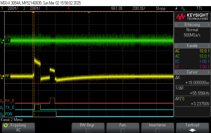
And here is the problem I discovered when I measure the GPIO lines and CSN after start the ESB-receiver:
I measure the pins at nrf21540 after esb_start_rx()
RX = 3v
TX = 0v
PDN = 3v
CSN = 3v <--- that should be 0V?
CSN described in the Product specs 4446_194 v1.0 / 2020-08-20 Page 12 , needs driven LOW explicit mentioned
but later version of the Product Spec 4446_194 v1.2 / 2022-01-28 CSN is a non't care (striped out) and not mentioned any more.
So documentation is a bit uncertain, and this change isn't mentioned in the document history.
I add for test in my main() a loop toggle receiver on (5s) off (5s) to check the CSN signal for each state:
bool rxon=false;
for (;;) {
if (rxon) {
esb_stop_rx();
}
else {
esb_start_rx();
}
rxon = !rxon;
LOG_DBG("RX is %s", rxon?"on":"off" );
k_sleep(K_MSEC(5000));
}
RTT-Viewer:
[00:00:55.004,821] <dbg> esb_prx: main: RX is off ----> and the CSN pin is 0V
[00:01:00.004,974] <dbg> esb_prx: main: RX is on -----> and the CSN pin is 3V
This is the result.
Please have a look into it.
With kind regards
Chris