BLE Antenna Issues on Custom nRF52840 PCB – Need Help!

Hello folks,

I need some help troubleshooting a BLE antenna issue on our custom nRF52840 PCB. Any insights would be greatly appreciated!

Issue:

  • BLE sometimes advertises on a mobile phone but disappears after a few seconds.
  • Other times, it doesn’t advertise at all.
  • Device is not consistently connectable.
  • We suspect the Pi filter matching may be causing the problem.

Troubleshooting So Far:

MCU Check: Blink program works, confirming the MCU is functional.
Antenna Tests:

  • External FPC antenna sometimes advertises but won’t connect; other times, it doesn’t advertise at all.
  • Tried multiple FPC antennas from a local supplier—same issue persists.
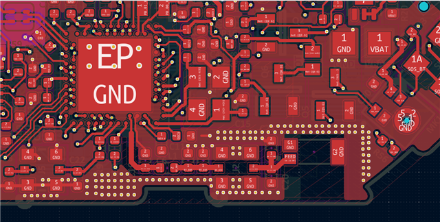
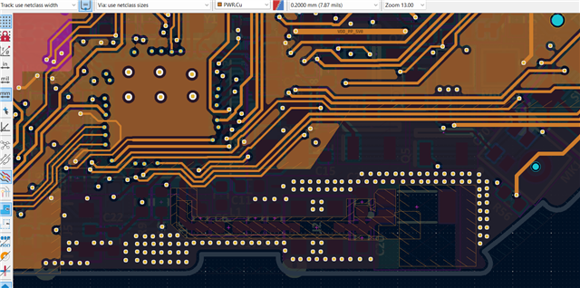
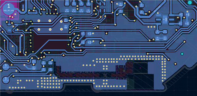
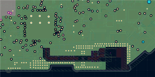
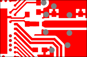
PCB Details:

4-layer board

  • Top Layer: Ground Plane
  • 2nd Layer: Ground Plane
  • 3rd Layer: Power Plane
  • 4th Layer: Ground Plane

    Antenna Setup:
  • Ceramic Antenna: W3008
  • External FPC Antenna: (Locally sourced, inconsistent performance)

Small blue diamond Pi Filter Matching Calculations – Need guidance on adjusting the matching network for better RF performance.
Small blue diamond General BLE RF Debugging Tips for custom PCBs.

I can provide schematics, layout snapshots, or test results if needed. We don't have inhouse VNA or Spectrum Analyzer only oscilloscope. 

Thanks in advance for your help! 

7002.Beacon.zip

Parents
  • I enabled the internal RC oscillator, and the BLE started advertising on one board (Mounted nRF52 components only). However, the other board is still not working. The BLE does not function on the other PCB, even though all components are mounted 

    How to fix oscillator Issue? Do anyone see Issues with Oscillator placement. Here is part number - 

    • TSX-3225_32.0000MF10Z-W6
    • ABS06-107-32.768KHZ-T 
  • Hi,

    There are a couple of issues with the RF part of the layout:

    • The shut capacitor closes to the SoC must be grounded to only the VSS_PA pin and the center GND pad, and not to the main ground fill. Here is a snippet from the refrence desing showing the correct way to ground this capacitor:

      This capacitor should also be moved closer to the SoC.
    • There is no ground under the RF trace, we recommend only having a cutout under RF path on the internal layers and keeping the bottom layer ground fill.
    • There are very few GND vias in the center GND pad, we recommend at least a 3x3 grid.

    These issues will impact the RF performance, the output power will probably be lower and the spurious emissions will be higher. But it should still be possible to see the advertisements at a short range.

    The onboard antenna will probably need to be tuned. The antenna datasheet recommend only one shunt capacitor, but from my experience with this antenna a full Pi network should be used instead.


    What is the load capacitance on the crystals?

    Based on the part numbers the 32MHz crystal needs 20pF capacitors and the 32.768kHz 4pF.

    These numbers are based on the following equation:

    C_cap = 2*CL - C_pin,

    Where CL is listed in the crystal datasheet and C_pin is 4pF for the nRF52 series.

    The frequency accuracy of the 32MHz crystal directly impacts the frequency accuracy of the radio. If this crystal is loaded incorrectly the radio carrier frequency may be offset to much leading to the advertising packages not being picked up by the receiver.


    Best regards,

    Bendik


    Best

Reply
  • Hi,

    There are a couple of issues with the RF part of the layout:

    • The shut capacitor closes to the SoC must be grounded to only the VSS_PA pin and the center GND pad, and not to the main ground fill. Here is a snippet from the refrence desing showing the correct way to ground this capacitor:

      This capacitor should also be moved closer to the SoC.
    • There is no ground under the RF trace, we recommend only having a cutout under RF path on the internal layers and keeping the bottom layer ground fill.
    • There are very few GND vias in the center GND pad, we recommend at least a 3x3 grid.

    These issues will impact the RF performance, the output power will probably be lower and the spurious emissions will be higher. But it should still be possible to see the advertisements at a short range.

    The onboard antenna will probably need to be tuned. The antenna datasheet recommend only one shunt capacitor, but from my experience with this antenna a full Pi network should be used instead.


    What is the load capacitance on the crystals?

    Based on the part numbers the 32MHz crystal needs 20pF capacitors and the 32.768kHz 4pF.

    These numbers are based on the following equation:

    C_cap = 2*CL - C_pin,

    Where CL is listed in the crystal datasheet and C_pin is 4pF for the nRF52 series.

    The frequency accuracy of the 32MHz crystal directly impacts the frequency accuracy of the radio. If this crystal is loaded incorrectly the radio carrier frequency may be offset to much leading to the advertising packages not being picked up by the receiver.


    Best regards,

    Bendik


    Best

Children
No Data
Related