
Hello, Nordic team.
We started to fight with the nrf52-ble-image-transfer-demo repo (congratulations on the project, ovrebekk).
We are using the nRF52840 DK (PCA10056, 3.0.2, 2024.21) and the on Win10 with SDK 16.0.0 + s140_nrf52_7.0.1_softdevice.hex, and we ordered and are waiting for a J-Ling V9 for debugging (unfortunately, it did not come with the DK).
We programmed the included .hex file (nrf52-ble-image-transfer-demo/tree/master/hex/app_hex image_transfer_demo_pca10056_s140.hex and image_transfer_demo_pca10056_s140_side_header.hex), and we cannot see the Blueetoth device “Camera Demo v2” with the Android App.
We also compile the code, but again, we do not get any feedback neither via Serial Terminal (v1.4.3).
Could you provide any advice?
We have not configured the solder bridges SB10-15 and SB20-25 yet, as suggested,
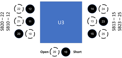
, because after checking the DK schematic we understand it is only required by the front header configuration.
We expect to get exciting results with this project.
Thank you very much!


