How to verify that the 32MHZ crystal is actually working (nRF52832?

I am using nRF connect SDK v2.9.0 with a custom developed board that looks like this:
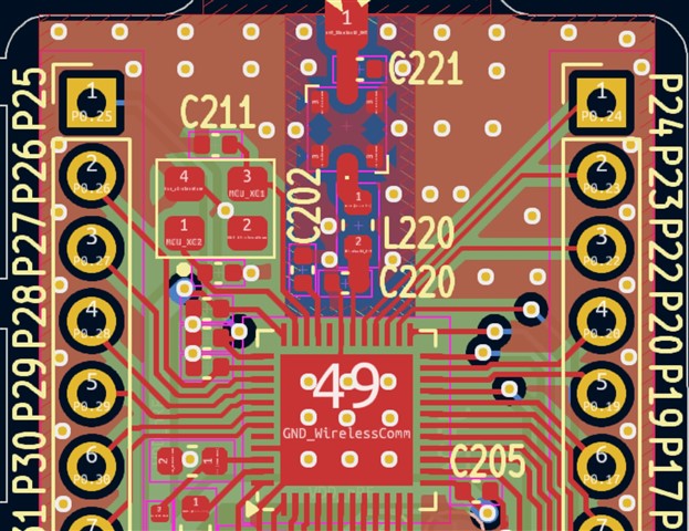
I tried the 'Bluetooth LE LED Button service' sample as it's and noticed that nothing was working. I grapped my logic analyzer and hooked it up onto the 32MHZ but nothing is showing. I mean other functionalities like zepyrRTOS, PWM, GPIOs, I2C, etc...  are working successfully but not BLE.

does the nRF52832 have an internal clock through which it works by default and if so, how does it use the external clock. what is the first thing to debug?

this is the crystal I am using:

https://www.lcsc.com/product-detail/Crystals_YXC-Crystal-Oscillators-X322532MOB4SI_C9009.html 

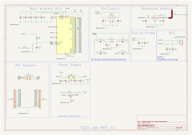
and these are the schematics:
Parents Reply Children
  • abdosalm said:
    Sorry for the late reply but I used a spectrum analyzer to make sure there was a signal being transmitted and I actually could see some peaks temporarily in the 2.4 to 2.5 GHZ bandwidth.

    This is not good enough, there are channels and specific frequencies so if there is an offset it might cause poor BLE performance ans it might just be bordering on acceptable results.

    This might also be the reason why device only works with\shows up on some devices and not others as sometimes there is a similar offset on some devices that work in favor for them. 


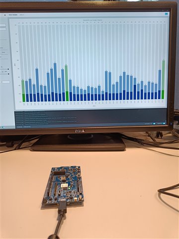
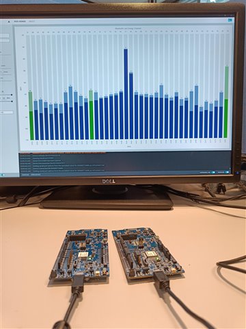
    Also its not just the antenna, its the whole RF performance we want to look at, so the clock and the emission, so maybe you could share what you saw on he spectrum analyzer?  Using the hex file i provided, as it will give a clear result that is easy to evaluate.

    Regards,
    Jonathan

  • Sorry for the late reply,

    When you first replied above with the '.hex' file to be flashed onto the target. When I tried to do it via black magic debugger, the debugger gave me an error but I tried to do it again today with segger jlink and it was downloaded successfully. 

    Unfortunately, I have damaged all of my UFL male PCB connectors and I have ordered some that are expected to arrive in 20 days, until then, I can think of nothing to do to debug my problem. once the connectors arrive, I will keep you updated on my problem.

  • abdosalm said:
    Unfortunately, I have damaged all of my UFL male PCB connectors

    As long as the antenna works you should be able to get some results, as you see from the images i shared there is no need to use the UFL connector here,  so no ned to connect the two units.

    Regards,
    Jonathan

  • Got it.

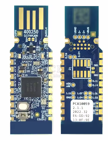
    But there still exists a small problem, should be the unit that's it to be connected to the RSSI app to have a tuned antenna which I don't have. That's why I have ordered the nRF52840 Module USB Dongle like in the image:

    to use it as a packet sniffer, or don't I have to?

  • We are only interested in seeing if the device works to some extent, even with a poorly tuned antenna you might still see something and could still get some range. But that we dont know, so the antenna might work fine. 

    Also with the hex file i shared we are not looking to sniff packets, we only look at the transmitted signal, there is no data there. Only a continues wave. 

    If  you have a nrf52DK and your custom board then that is enough to do the test. 


    Regards,
    Jonathan

Related