Hi,
I'm working on an indoor positioning system using an nRF5340 and a CHW1010-ANT1 antenna array. I'm receiving IQ samples from BLE CTE packets and using them to calculate the AoA.
When I manually input IQ values, the AoA is correct and stable. However, when I use live IQ samples from the receiver, the AoA values fluctuate significantly, even though the transmitter and receiver are stationary.
As I understood it, the first 8 samples are from the reference period and should not be used to calculate the AoA and the first sample to be used (at index 8) is from antenna idx 1 and not 0 since 0 is used in the reference period. So the pattern goes 0 - 0 - 0 - 0 - 0- 0 - 0 - 0 - 1 - 2 - 3 - 4 - 5 - 6 - 7 - 0 - 1 - etc. Am I missing something here?
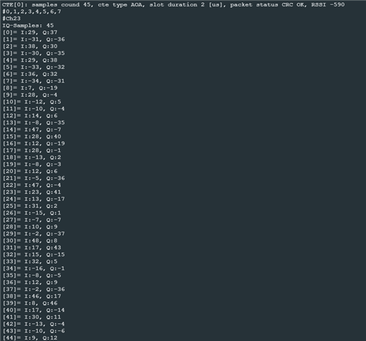
Below are some of the IQ samples I get.
Setup:
- Transmitter - nRF5340 sending BLE CTE signals
- Receiver - nRF5340 with CHW1010-ANT1 antenna array
- Antenna patches spacing - 5 cm
- UART - 115200 baud
- Antenna pattern - 0, 2, 4, 6, 8, 10, 12, 14
IQ sample values received:
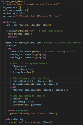
Read from UART func:
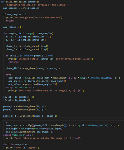
Calculate AoA func:
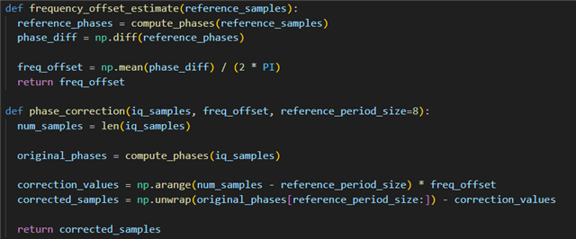
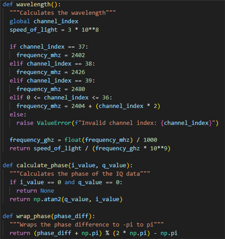
Wavelength, Phase calc, and Phase wrap funcs:
I assume that the logic is correct since manually set values are showing the correct AoA.
Grateful for any help!