
Hei guys,
this is my environment:
-
nrf52832 on custom board.
-
SDK 9.2
-
SD 132 1.0..0-3 preloaded in SD memory region
-
OLED with no MISO line
-
PINS configuration: CLK P04 CS P03 MOSI P05
The OLED needs one byte transfer. Due to this I tried to implement workaround PAN58 that another user asked but with no effect, the spi_master_event_handler() is never called. Here attached image of the serial comunication needed by the OLED:
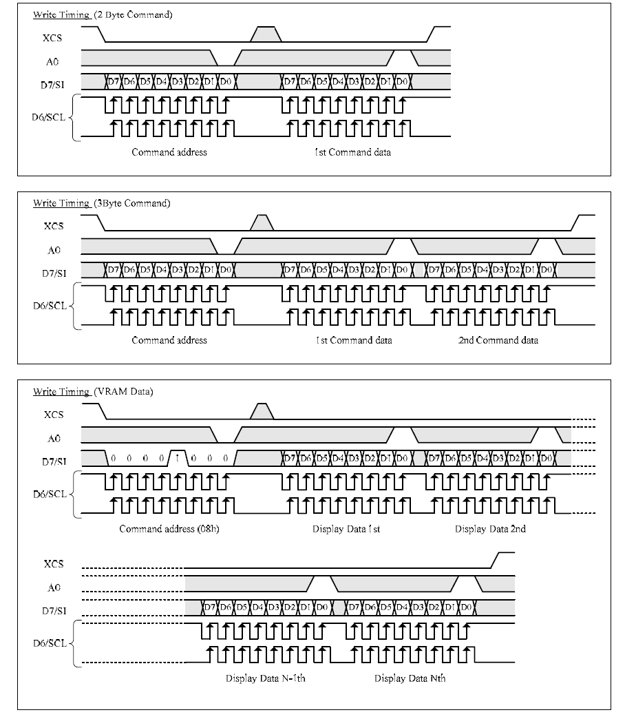
where XCS -> CS, A0 command select, D7/SI is MOSI, D6/SCL is CLK.
Now, the OLED needs a particular init sequence transferring data. Problem is that nothing seems to be transferred and, as already mentioned, evt_done is never reached. This result in a reset of the chip itself after a while.
Here the code implemented:
nrf_ppi_channel_t ppi_channel;
//OLED pin definition
#define OLED_ON					2
#define OLED_XRES				7
#define OLED_A0					6
#define OLED_MOSI				5
#define OLED_CS					3
#define OLED_CLK			    4

//setting up the SPI based on the spi_master_with_spi_slave example
//uses DMA
#if (SPI0_ENABLED == 1)
		static const nrf_drv_spi_t m_spi_master = NRF_DRV_SPI_INSTANCE(0);

#else
		#error "No SPI enabled."
#endif

static volatile bool m_transfer_completed = true; /**< A flag to inform about completed transfer. */

/**@brief Function for SPI master event callback.
 *
 * Upon receiving an SPI transaction complete event, checks if received data are valid.
 *
 * @param[in] spi_master_evt    SPI master driver event.
 */
static void spi_master_event_handler(nrf_drv_spi_event_t event)
{
		uint32_t err_code = NRF_SUCCESS;
		switch (event)
		{
				//if event is equal to NRF_DRV_SPI_EVENT_DONE, then this block is executed to check if data is valid
							case NRF_DRV_SPI_EVENT_DONE:

						//disable the ppi channel
						err_code = nrf_drv_ppi_channel_disable(ppi_channel);

						//disable a GPIOTE output pin task.
						nrf_drv_gpiote_out_task_disable(OLED_CLK);

						// Check if data are valid.
						/*err_code = bsp_indication_set(BSP_INDICATE_RCV_OK);
						APP_ERROR_CHECK(err_code);*/

						// Inform application that transfer is completed.
						m_transfer_completed = true;
						break;

								//if event is not equal to NRF_DRV_SPI_EVENT_DONE, then nothing happens
				default:
						// No implementation needed.
						break;
		}
}


/**@brief Function for initializing bsp module.
 */
void bsp_configuration()
{

		uint32_t err_code = NRF_SUCCESS;

		NRF_CLOCK->LFCLKSRC            = (CLOCK_LFCLKSRC_SRC_Xtal << CLOCK_LFCLKSRC_SRC_Pos);
		NRF_CLOCK->EVENTS_LFCLKSTARTED = 0;
		NRF_CLOCK->TASKS_LFCLKSTART    = 1;

		while (NRF_CLOCK->EVENTS_LFCLKSTARTED == 0)
		{
				// Do nothing.
		}
		/*APP_TIMER_INIT(APP_TIMER_PRESCALER, APP_TIMER_MAX_TIMERS, APP_TIMER_OP_QUEUE_SIZE, NULL);
		err_code = bsp_init(BSP_INIT_LED, APP_TIMER_TICKS(100, APP_TIMER_PRESCALER), NULL);
		APP_ERROR_CHECK(err_code);*/
}


void in_pin_handler(nrf_drv_gpiote_pin_t pin, nrf_gpiote_polarity_t action)
{
		nrf_drv_gpiote_out_toggle(OLED_CLK);
}

/**@brief Functions prepares buffers and starts data transfer
 *
 * @param[in] p_tx_data     A pointer to a buffer TX.
 * @param[in] p_rx_data     A pointer to a buffer RX.
 * @param[in] len           A length of the data buffers.
 */
static void spi_send_recv(uint8_t * const p_tx_data,
													uint8_t * const p_rx_data,
													const uint16_t  len)
{

				uint32_t err_code;
		NRF_SPIM_Type * p_spim = m_spi_master.p_registers;

		if (len == 1){
						ret_code_t err_code;
nrf_gpio_pin_clear(OLED_CS);
						// initializes the GPIOTE channel so that SCK toggles generates events
						nrf_drv_gpiote_in_config_t config = GPIOTE_CONFIG_IN_SENSE_TOGGLE(true);
						err_code = nrf_drv_gpiote_in_init(OLED_CLK, &config, in_pin_handler);
						APP_ERROR_CHECK(err_code);

						//allocates the first unused PPI Channel
						err_code = nrf_drv_ppi_channel_alloc(&ppi_channel);
						APP_ERROR_CHECK(err_code);

						err_code = nrf_drv_ppi_channel_assign(ppi_channel, nrf_drv_gpiote_in_event_addr_get(OLED_CLK), (uint32_t)&p_spim->TASKS_STOP);
						APP_ERROR_CHECK(err_code);


						//enable the PPI channel.
						err_code = nrf_drv_ppi_channel_enable(ppi_channel);
						APP_ERROR_CHECK(err_code);

						//enable the GPIOTE output pin task.
						nrf_drv_gpiote_in_event_enable(OLED_CLK, false);

						//Start transfer of data
						err_code = nrf_drv_spi_transfer(&m_spi_master, p_tx_data, len, p_rx_data, len);
						APP_ERROR_CHECK(err_code);


						//uninitializes the gpiote channel
						//the gpiote channel is represented by a 32-bit variable
						//not sure if we need to unintitialize the pin, or if we can just disable it
						//disable a GPIOTE output pin task.
						nrf_drv_gpiote_out_task_disable(OLED_CLK);


nrf_gpio_pin_set(OLED_CS);
				}
				else{
						// Start transfer.
						err_code = nrf_drv_spi_transfer(&m_spi_master, p_tx_data, len, p_rx_data, len);
						APP_ERROR_CHECK(err_code);
				}

		nrf_delay_ms(1);
}

void  oledWriteData(uint8_t byteToSend, uint8_t comm) {


	if(comm == 1)
	{
		nrf_gpio_pin_set(OLED_A0);
	}
	else
	{
		nrf_gpio_pin_clear(OLED_A0);
	}
	uint8_t write_buffer[1];
	write_buffer[0] = byteToSend;
	spi_send_recv(write_buffer,NULL,1);
	nrf_gpio_pin_set(OLED_A0);
}

void oledInit(void)
{
	oledWriteData(0x01, 1);
	nrf_delay_ms(1);
	oledWriteData(0x02, 1);
	oledWriteData(0x00, 0);

	oledWriteData(0x07, 1);
	oledWriteData(0x00, 0);

	oledWriteData(0x09, 1);
	oledWriteData(0x00, 0);

	oledWriteData(0x10, 1);
	oledWriteData(0x04, 0); //Here it blocks anyway, some buffers full?

	oledWriteData(0x12, 1);
	oledWriteData(0x65, 0);

	oledWriteData(0x13, 1);
	oledWriteData(0x00, 0);

	oledWriteData(0x14, 1);
	oledWriteData(0x00, 0);

	oledWriteData(0x16, 1);
	oledWriteData(0x00, 0);

	oledWriteData(0x17, 1);
	oledWriteData(0x00, 0);

	oledWriteData(0x18, 1);
	oledWriteData(0x04, 0);

	oledWriteData(0x1a, 1);
	oledWriteData(0x01, 0);

	oledWriteData(0x1c, 1);
	oledWriteData(0x00, 0);

	oledWriteData(0x1d, 1);
	oledWriteData(0x00, 0);

	oledWriteData(0x30, 1);
	oledWriteData(0x10, 0);
	oledWriteData(0x6f, 0);

	oledWriteData(0x32, 1);
	oledWriteData(0x00, 0);
	oledWriteData(0x26, 0);

	oledWriteData(0x34, 1);
	oledWriteData(0x00, 0);

	oledWriteData(0x35, 1);
	oledWriteData(0x0f, 0);

	oledWriteData(0x36, 1);
	oledWriteData(0x00, 0);

	oledWriteData(0x37, 1);
	oledWriteData(0x26, 0);


	oledWriteData(0x38, 1);
	oledWriteData(0x70, 0);


	oledWriteData(0x39, 1);
	oledWriteData(0x00, 0);


	oledWriteData(0x48, 1);
	oledWriteData(0x03, 0);

	oledWriteData(0xc3, 1);
	oledWriteData(0x00, 0);

	oledWriteData(0xc4, 1);
	oledWriteData(0x00, 0);

	oledWriteData(0xcc, 1);
	oledWriteData(0x00, 0);

	oledWriteData(0xcd, 1);
	oledWriteData(0x00, 0);

	oledWriteData(0xd0, 1);
	oledWriteData(0x80, 0);


	oledWriteData(0xd2, 1);
	oledWriteData(0x00, 0);

	oledWriteData(0xd9, 1);
	oledWriteData(0x00, 0);

	oledWriteData(0xdb, 1);
	oledWriteData(0x0f, 0);

	oledWriteData(0xdd, 1);
	oledWriteData(0x86, 0);


}
int main(void){

		bsp_configuration();

		nrf_gpio_cfg_output(OLED_ON);
		nrf_gpio_cfg_output(OLED_XRES);
		nrf_gpio_cfg_output(OLED_CS);
		nrf_gpio_cfg_output(OLED_CLK);
		nrf_gpio_cfg_output(OLED_MOSI);
		nrf_gpio_cfg_output(OLED_A0);

		nrf_gpio_pin_clear(OLED_ON);
		nrf_delay_ms(2);
		nrf_gpio_pin_clear(OLED_XRES);
		nrf_delay_ms(1);
		nrf_gpio_pin_set(OLED_XRES);
		nrf_delay_ms(1);
		nrf_gpio_pin_set(OLED_ON);

		//Configure SPI interface
		nrf_drv_spi_config_t const config =
		{
				#if (SPI0_ENABLED == 1)
						.sck_pin  = OLED_CLK,
						.mosi_pin = OLED_MOSI,
						.miso_pin = NRF_DRV_SPI_PIN_NOT_USED,
						.ss_pin   = NRF_DRV_SPI_PIN_NOT_USED,


				#endif
						.irq_priority = APP_IRQ_PRIORITY_LOW, //tells computer what to prioritize over other things
						.orc          = 0x00,
						.frequency    = NRF_DRV_SPI_FREQ_1M,
						.mode         = NRF_DRV_SPI_MODE_0,
						.bit_order    = NRF_DRV_SPI_BIT_ORDER_MSB_FIRST,
		};

		//Initialize SPI
		ret_code_t err_code = nrf_drv_spi_init(&m_spi_master, &config, spi_master_event_handler);
		APP_ERROR_CHECK(err_code);

		//initialize PPI and GPIOTE
		err_code = nrf_drv_ppi_init();
		APP_ERROR_CHECK(err_code);

		err_code = nrf_drv_gpiote_init();
		APP_ERROR_CHECK(err_code);

		//VARIABLES
		uint8_t numBytesReg = 0x1D;
		delay = 100;

		oledInit();
		//oledOn();
		//oledClear(0, 11, 0, 39, 0x01);
		//oledPrintBitmap(my_hello_message,0,39,0,96);
		//Infinite loop containing main functionality
		for(;;){
		 // nrf_delay_ms(delay);
			//SEGGER_RTT_WriteString(0, "Enterred For loop \n");


			if (m_transfer_completed)
			{
				//SEGGER_RTT_WriteString(0, "SPI transfer successful \n");
				m_transfer_completed = false;
			}
			nrf_delay_ms(1);
		}
}
Could you help me? It would be very appreciated.
Thanks.
