
HI there,
I've been following the DevAcademy Lesson 5 exercise example on SPI communication to get a nRF9161 DK (as a Master) and an ESP32 (as a Slave) to communicate synchronously. Right now I'm using a ESP32 DevKitC V4 for practicing, but eventually I will be using a ESP32 camera module to communicate the image trough SPI towards the nRF9161 board. So, the first problem I'm having so far is the device tree, which I'm attaching right here:
&i2c0 {	status = "disabled";};
&spi0 {	status = "disabled";};
&i2c1 {	status = "disabled";};
&uart1 { status = "disabled";};
&i2c2 { status = "disabled";};

&spi3 {
    status = "okay";
    compatible = "nordic,nrf-spim";
    pinctrl-0 = <&spi3_default>;
    pinctrl-1 = <&spi3_sleep>;
    pinctrl-names = "default", "sleep";
    cs-gpios = <&gpio0 18 GPIO_ACTIVE_LOW>;

    esp32: esp32@0 {
        compatible = "espressif,esp32";
        reg = <0>;
        spi-max-frequency = <5000000>;
    };
};

&gpio0 {
    status = "okay";
};

&spi2 {
    status = "disabled";
//    compatible = "nordic,nrf-spim";
//    pinctrl-0 = <&spi2_default>;
//    pinctrl-1 = <&spi2_sleep>;
//    pinctrl-names = "default", "sleep";
//    cs-gpios = <&gpio0 7 GPIO_ACTIVE_LOW>;
};

&spi1 {
    status = "disabled";
//    compatible = "nordic,nrf-spim";
//    pinctrl-0 = <&spi1_default>;
//    pinctrl-1 = <&spi1_sleep>;
//    pinctrl-names = "default", "sleep";
};

&pinctrl {
/*
    spi1_default: spi1_default {
        group1 {
            psels = <NRF_PSEL(SPIM_SCK, 0, 16)>,
                    <NRF_PSEL(SPIM_MOSI, 0, 17)>,
                    <NRF_PSEL(SPIM_MISO, 0, 19)>;
        };
    };
    spi1_sleep: spi1_sleep {
        group1 {
            psels = <NRF_PSEL(SPIM_SCK, 0, 16)>,
                    <NRF_PSEL(SPIM_MOSI, 0, 17)>,
                    <NRF_PSEL(SPIM_MISO, 0, 19)>;
            low-power-enable;
        };
    };
 */
/*
    spi2_default: spi2_default {
        group1 {
            psels = <NRF_PSEL(SPIM_SCK, 0, 16)>,
                    <NRF_PSEL(SPIM_MOSI, 0, 17)>,
                    <NRF_PSEL(SPIM_MISO, 0, 19)>;
        };
    };
    spi2_sleep: spi2_sleep {
        group1 {
            psels = <NRF_PSEL(SPIM_SCK, 0, 16)>,
                    <NRF_PSEL(SPIM_MOSI, 0, 17)>,
                    <NRF_PSEL(SPIM_MISO, 0, 19)>;
            low-power-enable;
        };
    };
 */

    spi3_default: spi3_default {
        group1 {
            psels = <NRF_PSEL(SPIM_SCK, 0, 16)>,
                    <NRF_PSEL(SPIM_MOSI, 0, 17)>,
                    <NRF_PSEL(SPIM_MISO, 0, 19)>;
        };
    };
    spi3_sleep: spi3_sleep {
        group1 {
            psels = <NRF_PSEL(SPIM_SCK, 0, 16)>,
                    <NRF_PSEL(SPIM_MOSI, 0, 17)>,
                    <NRF_PSEL(SPIM_MISO, 0, 19)>;
            low-power-enable;
        };
    };

};
As you can see, I've tried all the spi modules to get it to work, and for making the ESP32 slave work (following the steps done on the Lesson 5) I made a quick search to find a compatible driver for the ESP32 slave, ended up finding this one: https://docs.zephyrproject.org/latest/build/dts/api/bindings/spi/espressif%2Cesp32-spi.html#dtbinding-espressif-esp32-spi
In the overlay I used that same exact binding, but It shows this messages: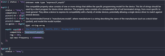
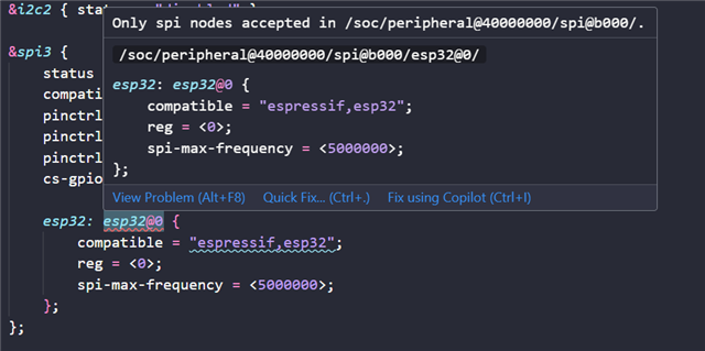
I don't seem to resolve the issues on those two captures, but that's not it. I'm pretty sure my main.c file is not working properly to get the data sent from the esp32 slave, I don't know how to make any kind of synchronization to get the correct data on the exact moment. I'm attaching aswell my main.c from nRF9161 and my main.c from ESP32:
#include <zephyr/kernel.h>
#include <zephyr/device.h>
#include <zephyr/drivers/spi.h>
#include <zephyr/sys/printk.h>
#include <string.h>

/* Retreive the API-device structure */
#define SPIOP	SPI_WORD_SET(8) | SPI_TRANSFER_MSB
// struct spi_dt_spec spispec = SPI_DT_SPEC_GET(DT_NODELABEL(esp32), SPIOP, 0);

// Definir el dispositivo SPI3
#define SPI_DEV_NODE DT_NODELABEL(spi3)

// Obtener el dispositivo SPI
static const struct device *spi_dev = DEVICE_DT_GET(SPI_DEV_NODE);

// Configuración del SPI con control automático de CS
struct spi_cs_control spi_cs = {
    .gpio = SPI_CS_GPIOS_DT_SPEC_GET(DT_NODELABEL(esp32)),
    .delay = 3, // Simula "cs_ena_posttrans" del ESP32
};

// Configuración del SPI
struct spi_config spi_cfg = {
    .frequency = 5000000,
    .operation = SPIOP,
    .slave = 0,
    .cs = &spi_cs, // Se asocia la estructura CS a la configuración del SPI
};

#define BUF_SIZE 2
static uint8_t recvbuf[BUF_SIZE] = {0};
static uint8_t sendbuf[BUF_SIZE] = {0xAA, 0xCA};

void main(void) {

    if (spi_cs.gpio.port == NULL || spi_cs.gpio.pin == -1) {
        printk("Error: El GPIO CS no esta correctamente configurado.\n");
        return;
    }

    struct spi_buf tx_buf = {
        .buf = sendbuf,
        .len = BUF_SIZE
    };
    struct spi_buf_set tx_buf_set = {
        .buffers = &tx_buf,
        .count = 1
    };

    struct spi_buf rx_buf = {
        .buf = recvbuf,
        .len = BUF_SIZE
    };
    struct spi_buf_set rx_buf_set = {
        .buffers = &rx_buf,
        .count = 1
    };

    printk("Initializing SPI in nRF9161 as Master...\n");

    if (!device_is_ready(spi_dev)) {
        printk("Error: SPI3 no está listo.\n");
        return;
    }

    while (1) {
        memset(recvbuf, 0, BUF_SIZE);

        int err = spi_transceive(spi_dev, &spi_cfg, &tx_buf_set, &rx_buf_set);

        if (err) {
            printk("Error in spi_transceive(), failed to receive: %d\n", err);
        } else {
            printk("Data received: %02X %02X\n", recvbuf[0], recvbuf[1]);
        }

        k_msleep(1000);
    }
}
#include <stdio.h>
#include <stdint.h>
#include <stddef.h>
#include <string.h>

#include "freertos/FreeRTOS.h"
#include "freertos/task.h"
#include "freertos/semphr.h"
#include "freertos/queue.h"

#include "lwip/sockets.h"
#include "lwip/dns.h"
#include "lwip/netdb.h"
#include "lwip/igmp.h"

#include "esp_wifi.h"
#include "esp_system.h"
#include "esp_event.h"
#include "nvs_flash.h"
#include "soc/rtc_periph.h"
#include "driver/spi_slave.h"
#include "esp_log.h"
#include "esp_spi_flash.h"
#include "driver/gpio.h"

// Pins in use
#define GPIO_MOSI 12
#define GPIO_MISO 13
#define GPIO_SCLK 15
#define GPIO_CS 14

uint8_t i = 0; // Counter

// Main application
void app_main(void)
{
    // Configuration for the SPI bus
    spi_bus_config_t buscfg = {
        .mosi_io_num = GPIO_MOSI,
        .miso_io_num = GPIO_MISO,
        .sclk_io_num = GPIO_SCLK,
        .quadwp_io_num = -1,
        .quadhd_io_num = -1,
    };

    // Configuration for the SPI slave interface
    spi_slave_interface_config_t slvcfg = {
        .mode = 0,
        .spics_io_num = GPIO_CS,
        .queue_size = 3,
        .flags = 0,
    };

    // Initialize SPI slave interface
    spi_slave_initialize(HSPI_HOST, &buscfg, &slvcfg, SPI_DMA_DISABLED);

    // SPI variables
    uint8_t sendbuf[2];
    uint8_t recvbuf[2];
    spi_slave_transaction_t t;
    t.length = sizeof(sendbuf) * 8;
    t.tx_buffer = sendbuf;
    t.rx_buffer = recvbuf;

    printf("Slave transmission:\n");
    while (1)
    {
        sendbuf[0] = i;
        sendbuf[1] = 0xAC;
        ESP_ERROR_CHECK_WITHOUT_ABORT(spi_slave_transmit(HSPI_HOST, &t, portMAX_DELAY));
        printf("Transmitted: %02x %02x\n", sendbuf[0], sendbuf[1]);
        printf("Received: %02x %02x\n", recvbuf[0], recvbuf[1]);
        vTaskDelay(1000 / portTICK_PERIOD_MS);
        i++;
    }
}
This is the current project I'm working on, which does not work at all even wired correctly. A previous work that I have done and got to work (not synchronized, sometimes Master received Slave's data but not all the time), but it's not working okay. I'm attaching it here aswell if it could help visualizing any ideas to get my job to work properly.
Slave ESP32 main.c:
#include <stdio.h>
#include <stdint.h>
#include <stddef.h>
#include <string.h>

#include "freertos/FreeRTOS.h"
#include "freertos/task.h"
#include "freertos/semphr.h"
#include "freertos/queue.h"

#include "lwip/sockets.h"
#include "lwip/dns.h"
#include "lwip/netdb.h"
#include "lwip/igmp.h"

#include "esp_wifi.h"
#include "esp_system.h"
#include "esp_event.h"
#include "nvs_flash.h"
#include "soc/rtc_periph.h"
#include "driver/spi_slave.h"
#include "esp_log.h"
#include "esp_spi_flash.h"
#include "driver/gpio.h"

// Pins in use
#define GPIO_MOSI 12
#define GPIO_MISO 13
#define GPIO_SCLK 15
#define GPIO_CS 14

uint8_t i = 0; // Counter

// Main application
void app_main(void)
{
    // Configuration for the SPI bus
    spi_bus_config_t buscfg = {
        .mosi_io_num = GPIO_MOSI,
        .miso_io_num = GPIO_MISO,
        .sclk_io_num = GPIO_SCLK,
        .quadwp_io_num = -1,
        .quadhd_io_num = -1,
    };

    // Configuration for the SPI slave interface
    spi_slave_interface_config_t slvcfg = {
        .mode = 0,
        .spics_io_num = GPIO_CS,
        .queue_size = 3,
        .flags = 0,
    };

    // Initialize SPI slave interface
    spi_slave_initialize(HSPI_HOST, &buscfg, &slvcfg, SPI_DMA_DISABLED);

    // Variables SPI
    uint8_t sendbuf[2];
    uint8_t recvbuf[2];

    printf("Slave transmission:\n");

    while (1)
    {
        // Configurar el mensaje a enviar
        sendbuf[0] = i;     // Counter
        sendbuf[1] = 0xAC;

        // Limpiar la estructura de transacción
        spi_slave_transaction_t t;
        memset(&t, 0, sizeof(t));

        // Configurar buffers de transmisión y recepción
        t.length = sizeof(sendbuf) * 8;  // Longitud en bits
        t.tx_buffer = sendbuf;
        t.rx_buffer = recvbuf;

        // Esperar y realizar la transacción SPI
        ESP_ERROR_CHECK_WITHOUT_ABORT(spi_slave_transmit(HSPI_HOST, &t, portMAX_DELAY));

        // Imprimir datos enviados por el esclavo
        printf("Tx: %02x %02x\n", sendbuf[0], sendbuf[1]);

        // Imprimir datos recibidos del maestro
        printf("Rx: %02x %02x\n", recvbuf[0], recvbuf[1]);

        i++;

        // Esperar 1 segundo antes de la siguiente transmisión
        vTaskDelay(1000 / portTICK_PERIOD_MS);
    }
}
Master nRF9161DK main.c:
#include <zephyr/kernel.h>
#include <zephyr/device.h>
#include <zephyr/drivers/spi.h>
#include <zephyr/drivers/gpio.h>
#include <zephyr/sys/printk.h>
#include <string.h>

// Already seen spi3 not working, so I decided to use spi2 again to give it a try
#define SPI_DEV_NODE DT_NODELABEL(spi3)

// GPIO pin for the CS, but it is actually se3 in the overlay file
#define SPI_CS_NODE DT_NODELABEL(gpio0)
#define SPI_CS_PIN  7

// Both GPIO and SPI devices are found here
static const struct device *spi_dev = DEVICE_DT_GET(SPI_DEV_NODE);
static const struct device *gpio_dev = DEVICE_DT_GET(SPI_CS_NODE);

// Configuration for the SPI device
struct spi_config spi_cfg = {
    .frequency = 1000000,       // Comprobar la frecuencia del reloj en el esclavo, que se pone en 1MHz
    .operation = SPI_OP_MODE_MASTER | SPI_WORD_SET(8) | SPI_TRANSFER_MSB,   // Mode 0, CPOL=0, CPHA=0
    .slave = 0,
};

// Buffer size and buffer to store the received data
#define BUF_SIZE 2
static uint8_t recvbuf[BUF_SIZE] = {0};
static uint8_t sendbuf[BUF_SIZE] = {0xAA, 0xCA};

void main(void)
{
    struct spi_buf tx_buf = {
        .buf = sendbuf,
        .len = BUF_SIZE
    };
    struct spi_buf_set tx_buf_set = {
        .buffers = &tx_buf,
        .count = 1
    };

    // There is no need to declare a spi tx buf since we are only receiving data
    struct spi_buf rx_buf = {
        .buf = recvbuf,
        .len = BUF_SIZE
    };
    struct spi_buf_set rx_buf_set = {
        .buffers = &rx_buf,
        .count = 1
    };

    printk("Initializing SPI in nRF9161 as Master...\n");

    // Check all the modules used are available and ready to use
    if (!device_is_ready(spi_dev)) {
        printk("Error: SPI3 no está listo.\n");
        return;
    }
    if (!device_is_ready(gpio_dev)) {
        printk("Error: GPIO no está listo.\n");
        return;
    }

    // Here GPIO pin CS gets configured as output
    gpio_pin_configure(gpio_dev, SPI_CS_PIN, GPIO_OUTPUT);
    gpio_pin_set(gpio_dev, SPI_CS_PIN, 1);

    // Begining of the spi functionality (receiving data)
    while (1) {
        // I decided to use memset to clean the buffer before each iteration
        // so as to avoid any garbage data that could be present in the buffer
        memset(recvbuf, 0, BUF_SIZE);

        // CS pin is set to low to start the SPI communication
        gpio_pin_set(gpio_dev, SPI_CS_PIN, 0);
//       k_sleep(K_USEC(1));

        // Here the received data from spi is stored in the buffer (err checks for errors)
        int err = spi_transceive(spi_dev, &spi_cfg, &tx_buf_set, &rx_buf_set);

        // CS pin is set now to high to end the SPI communication
        gpio_pin_set(gpio_dev, SPI_CS_PIN, 1);

        if (err) {
            printk("Error in spi_read(), failed to receive: %d\n", err);
        } else {
            printk("Data received: %02X %02X\n", recvbuf[0], recvbuf[1]);
        }

        // Delay of 1 second before the next iteration
        k_msleep(1000);
    }
}
Maser nRF9161DK overlay:
&i2c0 {	status = "disabled";};
&spi0 {	status = "disabled";};
&i2c1 {	status = "disabled";};
&uart1 { status = "disabled";};
&i2c2 { status = "disabled";};

&spi3 {
    status = "okay";
    compatible = "nordic,nrf-spim";
    pinctrl-0 = <&spi3_default>;
    pinctrl-1 = <&spi3_sleep>;
    pinctrl-names = "default", "sleep";
    cs-gpios = <&gpio0 7 GPIO_ACTIVE_LOW>;
};

&gpio0 {
    status = "okay";
};

&spi2 {
    status = "disabled";
//    compatible = "nordic,nrf-spim";
//    pinctrl-0 = <&spi2_default>;
//    pinctrl-1 = <&spi2_sleep>;
//    pinctrl-names = "default", "sleep";
//    cs-gpios = <&gpio0 7 GPIO_ACTIVE_LOW>;
};

&spi1 {
    status = "disabled";
//    compatible = "nordic,nrf-spim";
//    pinctrl-0 = <&spi1_default>;
//    pinctrl-1 = <&spi1_sleep>;
//    pinctrl-names = "default", "sleep";
};

&pinctrl {
/*
    spi1_default: spi1_default {
        group1 {
            psels = <NRF_PSEL(SPIM_SCK, 0, 16)>,
                    <NRF_PSEL(SPIM_MOSI, 0, 17)>,
                    <NRF_PSEL(SPIM_MISO, 0, 19)>;
        };
    };
    spi1_sleep: spi1_sleep {
        group1 {
            psels = <NRF_PSEL(SPIM_SCK, 0, 16)>,
                    <NRF_PSEL(SPIM_MOSI, 0, 17)>,
                    <NRF_PSEL(SPIM_MISO, 0, 19)>;
            low-power-enable;
        };
    };
 */
/*
    spi2_default: spi2_default {
        group1 {
            psels = <NRF_PSEL(SPIM_SCK, 0, 16)>,
                    <NRF_PSEL(SPIM_MOSI, 0, 17)>,
                    <NRF_PSEL(SPIM_MISO, 0, 19)>;
        };
    };
    spi2_sleep: spi2_sleep {
        group1 {
            psels = <NRF_PSEL(SPIM_SCK, 0, 16)>,
                    <NRF_PSEL(SPIM_MOSI, 0, 17)>,
                    <NRF_PSEL(SPIM_MISO, 0, 19)>;
            low-power-enable;
        };
    };
 */

    spi3_default: spi3_default {
        group1 {
            psels = <NRF_PSEL(SPIM_SCK, 0, 16)>,
                    <NRF_PSEL(SPIM_MOSI, 0, 17)>,
                    <NRF_PSEL(SPIM_MISO, 0, 19)>;
        };
    };
    spi3_sleep: spi3_sleep {
        group1 {
            psels = <NRF_PSEL(SPIM_SCK, 0, 16)>,
                    <NRF_PSEL(SPIM_MOSI, 0, 17)>,
                    <NRF_PSEL(SPIM_MISO, 0, 19)>;
            low-power-enable;
        };
    };

};
