
Hello,
I am experiencing an issue while trying to connect an external flash memory (MX25R64) via the QSPI interface on an nRF52840-based custom board. My pin configuration differs from the one used in the official development kit.
Here is my pin setup:
qspi_default: qspi_default {
group1 {
psels = <NRF_PSEL(QSPI_SCK, 1, 12)>,
<NRF_PSEL(QSPI_IO0, 1, 11)>,
<NRF_PSEL(QSPI_IO1, 1, 10)>,
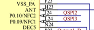
<NRF_PSEL(QSPI_IO2, 0, 10)>,
<NRF_PSEL(QSPI_IO3, 0, 9)>,
<NRF_PSEL(QSPI_CSN, 0, 31)>;
nordic,drive-mode = <NRF_DRIVE_H0H1>;
};
};
qspi_sleep: qspi_sleep {
group1 {
psels = <NRF_PSEL(QSPI_SCK, 1, 12)>,
<NRF_PSEL(QSPI_IO0, 1, 11)>,
<NRF_PSEL(QSPI_IO1, 1, 10)>,
<NRF_PSEL(QSPI_IO2, 0, 10)>,
<NRF_PSEL(QSPI_IO3, 0, 9)>;
low-power-enable;
};
group2 {
psels = <NRF_PSEL(QSPI_CSN, 0, 31)>;
low-power-enable;
bias-pull-up;
};
};
Flash configuration:
&qspi {
    status = "okay";
    pinctrl-0 = <&qspi_default>;
    pinctrl-1 = <&qspi_sleep>;
    pinctrl-names = "default", "sleep";

    mx25r64: mx25r6435f@0 {
        compatible = "nordic,qspi-nor";
        reg = <0>;
        writeoc = "pp4io";
        readoc = "read4io";
        sck-frequency = <2000000>;
        jedec-id = [ c2 28 17 ];
        sfdp-bfp = [ e5 20 f1 ff ff ff ff 03 44 eb 08 6b 08 3b 04 bb ee ff ff ff ff ff 00 ff ff ff 00 ff 0c 20 0f 52 10 d8 00 ff 23 72 f5 00 82 ed 04 cc 44 83 68 44 30 b0 30 b0 f7 c4 d5 5c 00 be 29 ff f0 d0 ff ff ];
        size = <67108864>;
        has-dpd;
        t-enter-dpd = <10000>;
        t-exit-dpd = <35000>;
    };
};
Upon initialization, I get the following error:
<err> qspi_nor: JEDEC id [00 00 00] expect [c2 28 17]
I suspect that the issue may be related to the fact that some of the assigned pins were originally used for NFC functionality. I attempted to reconfigure them as GPIO using:
nrfx_nvmc_word_write((uint32_t) & (NRF_UICR->NFCPINS),
                     (uint32_t)UICR_NFCPINS_PROTECT_Disabled);
However, this did not resolve the issue.
Could you please provide guidance on resolving this problem?
Thank you for your assistance!

