How can I measure LTEM TX power after the antenna impedance matching circuit

Hello,

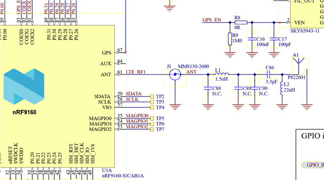
I’m currently working with a custom board based on the nRF9160 SiP, and I would like to measure the LTE-M TX power after the antenna impedance matching circuit. Ideally, I’d like to perform this measurement using an nRF9160 DK to help automate the RF testing process.

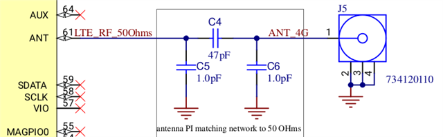
I’m aware that the %RFTEST TX AT command provides the transmitted power, but this measurement is taken at the antenna output, not after the matching circuit.

I was considering using the %RFTEST RX command on the development kit to capture the transmitted signal from the custom board. However, from my understanding, direct communication between two nRF9160 devices in this context is not supported.

Is there a recommended way to measure the TX power after the impedance matching circuit using a development kit, or any other method you suggest for automating this measurement?

Thank you in advance for your help!

Best regards,

Parents Reply Children
  • Carla31zv said:
    I would like to know—as mentioned in this ticket—whether it's possible to measure the transmitted signal power from one nRF9160 DK using another nRF9160 DK.

    Ok, understood. For this purpose, you should use a spectrum analyser, rather than a DK. The DK would likely not give very precise measurements, but I don't know what you're planning to use them for?

    If using the TX test %XRFTEST at any time, beware of the caution about restricted bands.

  • Precision in measurement is not a top priority for me. I was trying to use the AT command %XRFTEST RX to enable the RF receiver and measure the signal power sent by another devkit. However, I believe this isn't feasible because one devkit transmits on uplink frequencies, while the other receives on downlink frequencies

Related