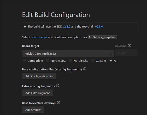
I bought a tiny board on Aliexpress from HolyIOT. It comes with an nRF52832 and an LIS2DH12 accelerometer. The silkscreen on the board says HOLYIOT-21011-v1.0.
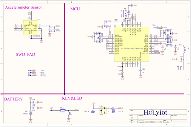
This schematic is not from the exact same board but is nearly identical. Sorry for the bad quality, it's the best I could find.
My goal is to obtain readings from the LIS2DH12 accelerometer. I tried using SPI first, but I had no luck.
Then, I tried with I2C since I'm more familiar with it. I paid attention to the accelerometer pins to enable the power supply, set it to I2C mode, and configure SA0.
  gpio_is_ready_dt(&i2c_on); //LIS2DH pin 2 (CS)
  gpio_pin_configure_dt(&i2c_on, GPIO_OUTPUT_ACTIVE);
  gpio_pin_set_dt(&i2c_on, 1);

  gpio_is_ready_dt(&lsb_sens); //LIS2DH pin 3 (SA0) -> i2c addr = 0x19
  gpio_pin_configure_dt(&lsb_sens, GPIO_OUTPUT_ACTIVE);
  gpio_pin_set_dt(&lsb_sens, 1);

  gpio_is_ready_dt(&supply); //LIS2DH pin 9 and 10 (VDD)
  gpio_pin_configure_dt(&supply, GPIO_OUTPUT_ACTIVE);
  gpio_pin_set_dt(&supply, 1);
With both SPI and I2C, I tried using Zephyr's official driver for this sensor, but I couldn't get it to work, apparently due to errors while reading the chip ID (WHO_AM_I register).
So, I then tried using the I2C shell to check this register manually. Here is the capture:

As you can see, the I2C scanner found the correct address of the sensor (0x19). I was also able to query the WHO_AM_I (0x0F) register, and the sensor responded correctly with 0x33, as stated in the datasheet.
At that point, I stopped trying with the sensor driver and decided to use the bare I2C functions instead. Here is an example:
  const struct device *dev = device_get_binding("i2c@40004000");

  uint8_t reg_addr[2] = {0x0f, 1};
  uint8_t data[2] = {0,0};

  if (dev == NULL) {
		printk("No device found\n");
		return;
	}

  ret = i2c_write(dev, reg_addr, 1, 0x19);
  if(ret != 0){
    printk("Failed to write from I2C device address %02x at Reg. %02x \n\r", dev_i2c.addr, reg_addr[0]);
  }
  ret = i2c_read(dev, data, 1, 0x19);

  if(ret != 0){
    printk("Failed to read from I2C device address %02x at Reg. %02x \n\r", dev_i2c.addr, reg_addr[0]);
  }
  printk("Byte: %02x\n", data[0]);
Here is another try:
#define I2C1_NODE DT_NODELABEL(mysensor)
static const struct i2c_dt_spec dev_i2c = I2C_DT_SPEC_GET(I2C1_NODE);

(...)

uint8_t reg_addr[2] = {0x0f, 1};
uint8_t data[2] = {0,0};

if (!device_is_ready(dev_i2c.bus)) {
	  printk("I2C bus %s is not ready!\n\r",dev_i2c.bus->name);
  }

  ret = i2c_write_read_dt(&dev_i2c, reg_addr, 1, data, 1);

  if(ret != 0){
    printk("Failed to read from I2C device address %02x at Reg. %02x \n\r", dev_i2c.addr, reg_addr[0]);
  }
  printk("Byte: %02x\n", data[0]);
This is part of the pinctrl:
	i2c1_default: i2c1_default {
		group1 {
			psels = <NRF_PSEL(TWIM_SDA, 0, 2)>,
							<NRF_PSEL(TWIM_SCL, 0, 5)>;
							bias-pull-up;
		};
	};

	i2c1_sleep: i2c1_sleep {
		group1 {
			psels = <NRF_PSEL(TWIM_SDA, 0, 2)>,
							<NRF_PSEL(TWIM_SCL, 0, 5)>;
							low-power-enable;
		};
	};
And this is from the DTS file (with the driver section commented out since I'm no longer using it):
&i2c1 {
	status = "okay";
	pinctrl-0 = <&i2c1_default>;
	pinctrl-1 = <&i2c1_sleep>;
	pinctrl-names = "default", "sleep";

	// lis2dh: lis2dh@19 {
  //   status = "okay";
	// 	compatible = "st,lis2dh";
	// 	reg = <0x19>;
	// 	irq-gpios = <&gpio0 6 GPIO_ACTIVE_HIGH>,  <&gpio0 7 GPIO_ACTIVE_HIGH>;
	// 	zephyr,deferred-init;
	// };
	mysensor: mysensor@19{
		compatible = "i2c-device";
		reg = < 0x19 >;
		label = "MYSENSOR";
	};
};
So, I concluded that the issue seems to be in the communication between the devices rather than in the driver itself. That's why I'm trying to focus on that. The problem is that I can't understand why it works through the shell but not with the bare I2C functions, which are almost identical to the ones used in the shell's source code.
Thanks in advance.