MODBUS not working, RS-485

Hello, I'm having problems trying to make the MODBUS RTU Client code work on my board.

I'm devoloping with nrf Connect SDK v2.1.0, using Visual Studio Code.

The board uses an nRF52832 microcontroller, it also has an SN65HVD72DRBR IC(which is like a max3485 module, with different footprint) for RS-485 communication. And I have connected on the other side a TUF-2000 flow meter.

The conection to the RS-485 IC is the following:

PO_02 -> D
PO_03 -> R
PO_04 -> DE
PO_06 -> RE

I have these definitions in the .dts file:

&uart0 {
	modbus-serial {
		compatible = "zephyr,modbus-serial";
		
	};
	status = "okay";
};

These definitions in the .overlay file:

aliases {
    pincarga0 = &pincarga;
	pinpg0 = &pinpg;
    ledrojo = &led0;
    ledazul = &led1;
    uartcaudal = &uart0;
};

&uart0 {
    compatible = "nordic,nrf-uart";
    current-speed = <9600>;
    tx-pin = <2>;
    rx-pin = <3>;
    label = "uart_caudal";
    modbus-serial {
        compatible = "zephyr,modbus-serial";
        status = "okay";
		de-gpios = < &gpio0 4 GPIO_ACTIVE_HIGH >;
        re-gpios = < &gpio0 6 GPIO_ACTIVE_LOW >;
        label = "zephyr_modbus_serial";
  };
};

I added the "label = "zephyr_modbus_serial"", in order for the firmware to compile this part:

#define MODBUS_NODE DT_COMPAT_GET_ANY_STATUS_OKAY(zephyr_modbus_serial)

static int init_modbus_client(void)
{
	const char iface_name[] = {DEVICE_DT_NAME(MODBUS_NODE)};

	client_iface = modbus_iface_get_by_name(iface_name);

	return modbus_init_client(client_iface, client_param);
}

This is the prj.conf part of the modbus_serial:

# UART
CONFIG_SERIAL=y
CONFIG_UART_INTERRUPT_DRIVEN=n
CONFIG_UART_ASYNC_API=y
CONFIG_MODBUS_SERIAL=y
CONFIG_MODBUS=y
CONFIG_MODBUS_ROLE_CLIENT=y
CONFIG_MODBUS_LOG_LEVEL_DBG=y

In the RTU Client example there is no initialization of the uart, nor the uart pins, this is very confusing to me. Seems to me that there is some kind of magic in the "@Arduino_serial" in the overlay file.

I tried adding the "@Arduino_serial" in my overlay or dts files but the firmware does not compile at all, so I kept using "@uart0" as my previous firmware used to work and added the modbus_serial to it.

So, what is the situation now? The firmware compiles, the funtions are called, everything happens except that there is no data coming off the RS-485 module.

Here is the code that uses this modbus client:

caudal_status_t caudal_obtener_lectura(caudal_mensaje_lectura_t *data)
{
  if (init_modbus_client()) {
		LOG_ERR("Modbus RTU client initialization failed");
		return 0;
	}
  uint16_t buffer[8];
  //Leer registro 1: caudal instantaneo
  int err = modbus_read_holding_regs(client_iface, 1, 1, buffer, 2);
  if (err != 0) {
  LOG_ERR("Reading holding register ID 1, 2 words: failed with error %d", err);
  }
  else
  {
    LOG_INF("Caudal instantaneo: %04X%04X", buffer[0], buffer[1]);
  }
  //Leer registro 9: caudal acumulado positivo
  err = modbus_read_holding_regs(client_iface, 1, 9, buffer, 2);
  if (err != 0) {
  LOG_ERR("Reading holding register ID 9, 2 words: failed with error %d", err);
  }
  else
  {
    LOG_INF("Caudal acumulado positivo: %04X%04X", buffer[0], buffer[1]);
  }
  //Leer registro 13: caudal acumulado negativo
  err = modbus_read_holding_regs(client_iface, 1, 13, buffer, 2);
  if (err != 0) {
  LOG_ERR("Reading holding register ID 9, 2 words: failed with error %d", err);
  }
  else
  {
    LOG_INF("Caudal acumulado negativo: %04X%04X", buffer[0], buffer[1]);
  }
  return CAUDAL_STATUS_OK;
}

The logged data in the Ozone Debugger shows rx_timeout:

[00787876] <inf> modbus_serial: RTU timeout 4010 us
[00787877] <dbg> modbus_serial: rtu_tx_adu: uart_buf
                                01 03 00 01 00 02 95 cb                          |........         
[00787878] <dbg> modbus_serial: rtu_tx_adu: Start frame transmission
[00787879] <inf> lorawan_manager: MBOX_GPE_LORAWAN_TX
[00789519] <wrn> modbus: Client wait-for-RX timeout
[00789519] <err> caudal: Reading holding register ID 1, 2 words: failed with error -116
[00789521] <dbg> modbus_serial: rtu_tx_adu: uart_buf
                                01 03 00 09 00 02 14 09                          |........         
[00789521] <dbg> modbus_serial: rtu_tx_adu: Start frame transmission
[00791162] <wrn> modbus: Client wait-for-RX timeout
[00791162] <err> caudal: Reading holding register ID 9, 2 words: failed with error -116
[00791164] <dbg> modbus_serial: rtu_tx_adu: uart_buf
[00792806] <wrn> modbus: Client wait-for-RX timeout
[00792807] <err> caudal: Reading holding register ID 9, 2 words: failed with error -116

I hooked up B, A, DE and RE lines with a logic analizer, this is observed on the moment th function init_modbus_client() is called:

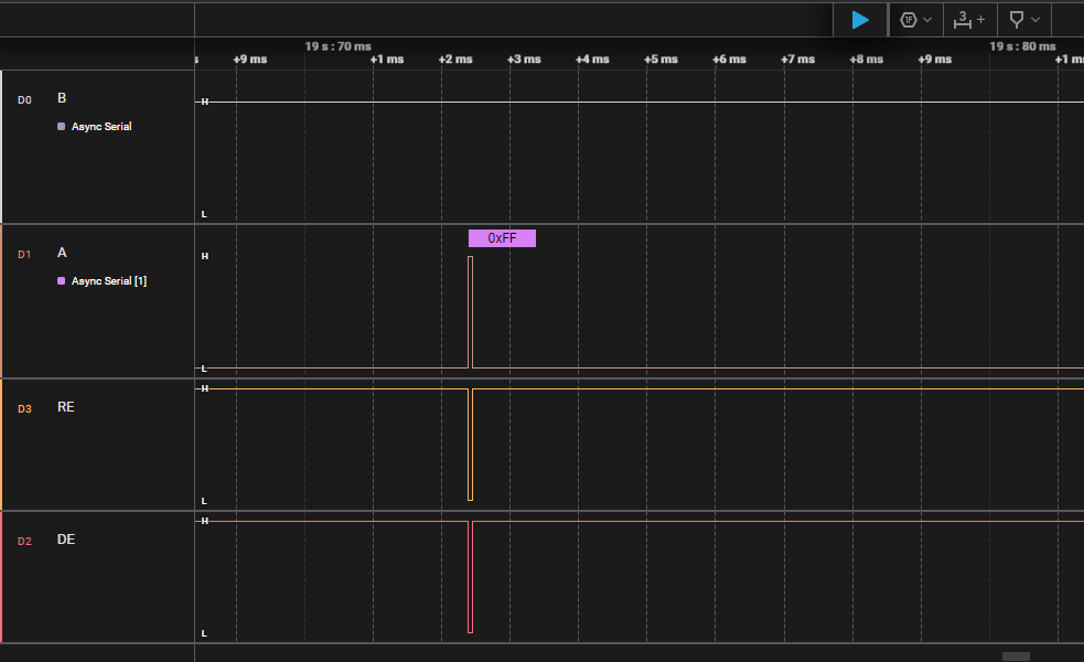
After this moment, there is no change in any of the lines (B, A, RE and DE).

I am very confused as to why there is nothing happening in any of the RS-485 lines. Maybe there is something not intialized correctly, or not initialized at all. I searched through the forum and the internet for answers, they got me this far...

Before all of these, I was using uart_tx function and handling the DE and RE pins separetly, which worked but was very flawed. So I started to look into modbus_serial implemtentation but haven't yet make it work.

If anyone has any inside on this problem I will appreciate it very much.

Parents
  • Well, it didn't work. I ended up fixing my basic implementation of modbus protocol, it works well but is very basic.

    If anyone finds it usefull, here it is:

    This is the .dts config for the uart and gpio:

    &gpio0 {
    	status = "okay";
    	gpio-controller;
      #gpio-cells = <2>;
    };
    
    &uart0 {
    	status = "okay";
    };

    This is the .overlay config:

      aliases {
        pinre0 = &pinre;
        pinde0 = &pinde;
        uartcaudal = &uart0;
      };
    
      pines {
    		compatible = "gpio-keys";
        
    		pinre: pin_485_re {
    			gpios = < &gpio0 6 GPIO_ACTIVE_HIGH >;
    			label = "PIN 485 RE";
    		};
    		pinde: pin_485_de {
    			gpios = < &gpio0 4 GPIO_ACTIVE_HIGH >;
    			label = "PIN 485 DE";
    		};
    };
    
    &uart0 {
      compatible = "nordic,nrf-uart";
      current-speed = <9600>;
      tx-pin = <2>;
      rx-pin = <3>;
      label = "uart_caudal";
    };

    This is the uart and gpio config in the prj.conf file:

    # GPIO
    CONFIG_GPIO=y
    
    # UART
    CONFIG_SERIAL=y
    CONFIG_UART_INTERRUPT_DRIVEN=n
    CONFIG_UART_ASYNC_API=y

    And here is the implementation I came up with following the modbus-rtu protocol from this website and the TUF-2000 datasheet.
    This device only accepts functions 0x03 and 0x06 of the modbus protocol, so I limited my effort only to those funtions alone.

    #include "caudal.h"
    
    #include <zephyr.h>
    #include <device.h>
    #include <devicetree.h>
    #include <drivers/uart.h>
    #include <drivers/gpio.h>
    #include <logging/log.h>
    #include <pm/device.h>
    #include "config.h"
    
    LOG_MODULE_REGISTER(caudal, LOG_LEVEL_INF);
    
    #define PIN_DE		                    DT_ALIAS(pinde0)
    #define PIN_RE		                    DT_ALIAS(pinre0)
    const struct gpio_dt_spec pin_de_485 = GPIO_DT_SPEC_GET(PIN_DE, gpios);
    const struct gpio_dt_spec pin_re_485 = GPIO_DT_SPEC_GET(PIN_RE, gpios);
    const struct device *uart_dev = DEVICE_DT_GET(DT_ALIAS(uartcaudal));
    
    caudal_config_t *paramsCaudal = NULL;
    uint8_t buffer_rx_async[500];
    int32_t caudal_ultimaLectura = 0;
    
    void uart_cb(const struct device *dev, struct uart_event *evt, void *user_data);
    void radar_llenar_buffer(void);
    int32_t caudal_convertir_real4_a_int32_t(uint16_t *buffer);
    void caudal_transceiver_read_holding_modbus(uint8_t dev_adr, uint16_t id_param, uint16_t param_len, uint8_t *rx_buffer);
    void caudal_transceiver_write_single_register_16bit_modbus(uint8_t dev_adr, uint16_t id_param, uint16_t data);
    void caudal_transceiver_write_single_register_32bit_modbus(uint8_t dev_adr, uint16_t id_param, uint32_t data);
    uint16_t calculate_crc16_Modbus(char *p, unsigned int length);
    
    typedef union{
      uint16_t u16;
      uint8_t u8[sizeof(uint16_t)];
    }Union16;
    
    
    typedef union{
      float f;
      uint8_t u8[sizeof(float)];
    }UnionFloat;
    
    caudal_status_t caudal_init(caudal_config_t *config) {
      paramsCaudal = config;
      int ret = 0;
      if (!device_is_ready(uart_dev)) {
        LOG_ERR("UART device not ready");
        return CAUDAL_STATUS_ERROR_NO_DEVICE;
      }
      if (!device_is_ready(pin_re_485.port)) {
        LOG_ERR("GPIO device not ready");
        return CAUDAL_STATUS_ERROR_NO_DEVICE;
      }
      if (!device_is_ready(pin_de_485.port)) {
        LOG_ERR("GPIO device not ready");
        return CAUDAL_STATUS_ERROR_NO_DEVICE;
      }
      ret = gpio_pin_configure_dt(&pin_re_485, GPIO_OUTPUT_HIGH);
      ret = gpio_pin_configure_dt(&pin_de_485, GPIO_OUTPUT_LOW);
      ret = uart_callback_set(uart_dev, uart_cb, NULL);
      if (ret) {
        LOG_ERR("UART callback set failed with %d", ret);
        return CAUDAL_STATUS_INIT_ERROR;
      }
      return CAUDAL_STATUS_OK;
    }
    
    void uart_cb(const struct device *dev, struct uart_event *evt, void *user_data) {
    	switch (evt->type) {
        case UART_TX_DONE: 
        case UART_TX_ABORTED: 
        case UART_RX_RDY:
        case UART_RX_BUF_REQUEST:
        case UART_RX_BUF_RELEASED: {
          break;
        }
        case UART_RX_DISABLED: {
          uart_rx_enable(uart_dev, buffer_rx_async, sizeof(buffer_rx_async), 500000);
          break;
        }
        case UART_RX_STOPPED:
        default: {
          break;
        }
    	}
    }
    
    caudal_status_t caudal_obtener_lectura(caudal_mensaje_lectura_t *data)
    {
      //Activar UART
      pm_device_action_run(uart_dev, PM_DEVICE_ACTION_RESUME);
      k_sleep(K_MSEC(100));
      //Leer datos de caudal
      Union32 buffer_rx;
      //caudal instantaneo
      caudal_transceiver_read_holding_modbus(paramsCaudal->dev_adr, 0, 2, buffer_rx.u8);
      caudal_ultimaLectura = buffer_rx.s32;//Convertir float a valor real
      data->caudal_instantaneo = caudal_ultimaLectura;
      //caudal acumulado positivo
      caudal_transceiver_read_holding_modbus(paramsCaudal->dev_adr, 8, 2, buffer_rx.u8);
      data->caudal_acumulado_positivo = buffer_rx.s32;
      //caudal acumulado negativo
      caudal_transceiver_read_holding_modbus(paramsCaudal->dev_adr, 12, 2, buffer_rx.u8);
      data->caudal_acumulado_negativo = buffer_rx.s32;
      //Multiplicador de totalizado
      caudal_transceiver_read_holding_modbus(paramsCaudal->dev_adr, 1437, 1, buffer_rx.u8);
      return CAUDAL_STATUS_OK;
    }
    
    void caudal_obtener_ultima_lectura(caudal_mensaje_lectura_t *data)
    {
      data->caudal_instantaneo = caudal_ultimaLectura;
    }
    
    void caudal_transceiver_read_holding_modbus(uint8_t dev_adr, uint16_t id_param, uint16_t param_len, uint8_t *rx_buffer)
    {
      Union16 id, len;
      id.u16 = id_param;
      len.u16 = param_len;
      //Armar comando MODBUS con id_param y param_len
      uint8_t cmd[8] = {dev_adr, 0x03, id.u8[1], id.u8[0], len.u8[1], len.u8[0], 0x00, 0x00};
      //Calcular CRC
      Union16 crc;
      crc.u16 = calculate_crc16_Modbus((char *)cmd, 6);
      cmd[6] = crc.u8[0];
      cmd[7] = crc.u8[1];
      printk("Cmd: ");
      for (int i = 0; i < sizeof(cmd); i++)
      {
        printk("%02X", cmd[i]);
        k_sleep(K_MSEC(1));
      }
      printk("\r\n");
      //Transmitir comando
      //Primero activar modulo RS-485 en modo TX
      gpio_pin_set_dt(&pin_de_485, 1);
      gpio_pin_set_dt(&pin_re_485, 1);
      k_sleep(K_MSEC(10));
      uart_tx(uart_dev, cmd, sizeof(cmd), 0);
      k_sleep(K_MSEC(1.3 * sizeof(cmd)));
      //Ahora activar modulo RS-485 en modo RX
      gpio_pin_set_dt(&pin_de_485, 0);
      gpio_pin_set_dt(&pin_re_485, 0);
      //Leer respuesta
      //Antes calcular size de la respuesta según param_len
      int rx_len = 3 + (param_len * 2) + 2;
      //Limpiar buffer_rx_async
      memset(buffer_rx_async, 0, sizeof(buffer_rx_async));
      k_sleep(K_MSEC(1));
      uart_rx_enable(uart_dev, buffer_rx_async, rx_len, 500000);
      k_sleep(K_MSEC((1.3 * rx_len) + 50));
      //Desactivar modulo RS-485
      gpio_pin_set_dt(&pin_de_485, 0);
      gpio_pin_set_dt(&pin_re_485, 1);
      k_sleep(K_MSEC(1));
      printk("Res: ");
      for (int i = 0; i < rx_len; i++)
      {
        printk("%02X", buffer_rx_async[i]);
        k_sleep(K_MSEC(1));
      }
      printk("\r\n");
      //Parsear respuesta
      memcpy(rx_buffer, &buffer_rx_async[3], param_len * 2);
      uart_rx_disable(uart_dev);
    }
    
    void caudal_transceiver_write_single_register_16bit_modbus(uint8_t dev_adr, uint16_t id_param, uint16_t data)
    {
      Union16 id, dat;
      id.u16 = id_param;
      dat.u16 = data;
      uint8_t cmd[8] = {dev_adr, 0x06, id.u8[1], id.u8[0], dat.u8[1], dat.u8[0], 0x00, 0x00};
      Union16 crc;
      crc.u16 = calculate_crc16_Modbus((char *)cmd, 6);
      cmd[6] = crc.u8[0];
      cmd[7] = crc.u8[1];
      printk("Cmd: ");
      for (int i = 0; i < sizeof(cmd); i++)
      {
        printk("%02X", cmd[i]);
        k_sleep(K_MSEC(1));
      }
      printk("\r\n");
      //Transmitir comando
      //Primero activar modulo RS-485 en modo TX
      gpio_pin_set_dt(&pin_de_485, 1);
      gpio_pin_set_dt(&pin_re_485, 1);
      k_sleep(K_MSEC(10));
      uart_tx(uart_dev, cmd, sizeof(cmd), 0);
      k_sleep(K_MSEC(1.3 * sizeof(cmd)));
      //Ahora activar modulo RS-485 en modo RX
      gpio_pin_set_dt(&pin_de_485, 0);
      gpio_pin_set_dt(&pin_re_485, 0);
      //Leer respuesta
      //Antes calcular size de la respuesta según param_len
      int rx_len = sizeof(cmd);
      //Limpiar buffer_rx_async
      memset(buffer_rx_async, 0, sizeof(buffer_rx_async));
      k_sleep(K_MSEC(1));
      uart_rx_enable(uart_dev, buffer_rx_async, rx_len, 500000);
      k_sleep(K_MSEC((1.3 * rx_len) + 50));
      //Desactivar modulo RS-485
      gpio_pin_set_dt(&pin_de_485, 0);
      gpio_pin_set_dt(&pin_re_485, 1);
      k_sleep(K_MSEC(1));
      printk("Res: ");
      for (int i = 0; i < rx_len; i++)
      {
        printk("%02X", buffer_rx_async[i]);
        k_sleep(K_MSEC(1));
      }
      printk("\r\n");
      uart_rx_disable(uart_dev);
    }
    
    void caudal_transceiver_write_single_register_32bit_modbus(uint8_t dev_adr, uint16_t id_param, uint32_t data)
    {
      Union32 temp;
      temp.u32 = data;
      caudal_transceiver_write_single_register_16bit_modbus(dev_adr, id_param, temp.u16[0]);
      caudal_transceiver_write_single_register_16bit_modbus(dev_adr, id_param + 1, temp.u16[1]);
    }
    
    /************************** CALCULO CRC 16 MODBUS **************************/
    const uint16_t crc_tab_8005_reflected[] =
    {
    	0x0000, 0xC0C1, 0xC181, 0x0140, 0xC301, 0x03C0, 0x0280, 0xC241,
    	0xC601, 0x06C0, 0x0780, 0xC741, 0x0500, 0xC5C1, 0xC481, 0x0440,
    	0xCC01, 0x0CC0, 0x0D80, 0xCD41, 0x0F00, 0xCFC1, 0xCE81, 0x0E40,
    	0x0A00, 0xCAC1, 0xCB81, 0x0B40, 0xC901, 0x09C0, 0x0880, 0xC841,
    	0xD801, 0x18C0, 0x1980, 0xD941, 0x1B00, 0xDBC1, 0xDA81, 0x1A40,
    	0x1E00, 0xDEC1, 0xDF81, 0x1F40, 0xDD01, 0x1DC0, 0x1C80, 0xDC41,
    	0x1400, 0xD4C1, 0xD581, 0x1540, 0xD701, 0x17C0, 0x1680, 0xD641,
    	0xD201, 0x12C0, 0x1380, 0xD341, 0x1100, 0xD1C1, 0xD081, 0x1040,
    	0xF001, 0x30C0, 0x3180, 0xF141, 0x3300, 0xF3C1, 0xF281, 0x3240,
    	0x3600, 0xF6C1, 0xF781, 0x3740, 0xF501, 0x35C0, 0x3480, 0xF441,
    	0x3C00, 0xFCC1, 0xFD81, 0x3D40, 0xFF01, 0x3FC0, 0x3E80, 0xFE41,
    	0xFA01, 0x3AC0, 0x3B80, 0xFB41, 0x3900, 0xF9C1, 0xF881, 0x3840,
    	0x2800, 0xE8C1, 0xE981, 0x2940, 0xEB01, 0x2BC0, 0x2A80, 0xEA41,
    	0xEE01, 0x2EC0, 0x2F80, 0xEF41, 0x2D00, 0xEDC1, 0xEC81, 0x2C40,
    	0xE401, 0x24C0, 0x2580, 0xE541, 0x2700, 0xE7C1, 0xE681, 0x2640,
    	0x2200, 0xE2C1, 0xE381, 0x2340, 0xE101, 0x21C0, 0x2080, 0xE041,
    	0xA001, 0x60C0, 0x6180, 0xA141, 0x6300, 0xA3C1, 0xA281, 0x6240,
    	0x6600, 0xA6C1, 0xA781, 0x6740, 0xA501, 0x65C0, 0x6480, 0xA441,
    	0x6C00, 0xACC1, 0xAD81, 0x6D40, 0xAF01, 0x6FC0, 0x6E80, 0xAE41,
    	0xAA01, 0x6AC0, 0x6B80, 0xAB41, 0x6900, 0xA9C1, 0xA881, 0x6840,
    	0x7800, 0xB8C1, 0xB981, 0x7940, 0xBB01, 0x7BC0, 0x7A80, 0xBA41,
    	0xBE01, 0x7EC0, 0x7F80, 0xBF41, 0x7D00, 0xBDC1, 0xBC81, 0x7C40,
    	0xB401, 0x74C0, 0x7580, 0xB541, 0x7700, 0xB7C1, 0xB681, 0x7640,
    	0x7200, 0xB2C1, 0xB381, 0x7340, 0xB101, 0x71C0, 0x7080, 0xB041,
    	0x5000, 0x90C1, 0x9181, 0x5140, 0x9301, 0x53C0, 0x5280, 0x9241,
    	0x9601, 0x56C0, 0x5780, 0x9741, 0x5500, 0x95C1, 0x9481, 0x5440,
    	0x9C01, 0x5CC0, 0x5D80, 0x9D41, 0x5F00, 0x9FC1, 0x9E81, 0x5E40,
    	0x5A00, 0x9AC1, 0x9B81, 0x5B40, 0x9901, 0x59C0, 0x5880, 0x9841,
    	0x8801, 0x48C0, 0x4980, 0x8941, 0x4B00, 0x8BC1, 0x8A81, 0x4A40,
    	0x4E00, 0x8EC1, 0x8F81, 0x4F40, 0x8D01, 0x4DC0, 0x4C80, 0x8C41,
    	0x4400, 0x84C1, 0x8581, 0x4540, 0x8701, 0x47C0, 0x4680, 0x8641,
    	0x8201, 0x42C0, 0x4380, 0x8341, 0x4100, 0x81C1, 0x8081, 0x4040
    };
    
    uint16_t update_crc16_reflected(const uint16_t *table, uint16_t crc, char c )
    {
    	uint16_t short_c;
    
    	short_c  = 0x00ff & (uint16_t) c;
    
    	/* Reflected form */
    	return (crc >> 8) ^ table[(crc ^ short_c) & 0xff];
    }
    
    uint16_t update_crc16_A001( uint16_t crc, char c )
    {
    	return update_crc16_reflected(crc_tab_8005_reflected,crc,c);
    }
    
    uint16_t calculate_crc16_Modbus(char *p, unsigned int length)
    {
    	uint16_t crc;
    	unsigned int i;
    
    	crc = 0xFFFF;
    
    	for (i=0; i < length; i++)
    	{
    		crc = update_crc16_A001(crc,*p++);
    	}
    	return crc;
    }
    

    This code works fine, but I have no idea if it would work in other devices.

Reply
  • Well, it didn't work. I ended up fixing my basic implementation of modbus protocol, it works well but is very basic.

    If anyone finds it usefull, here it is:

    This is the .dts config for the uart and gpio:

    &gpio0 {
    	status = "okay";
    	gpio-controller;
      #gpio-cells = <2>;
    };
    
    &uart0 {
    	status = "okay";
    };

    This is the .overlay config:

      aliases {
        pinre0 = &pinre;
        pinde0 = &pinde;
        uartcaudal = &uart0;
      };
    
      pines {
    		compatible = "gpio-keys";
        
    		pinre: pin_485_re {
    			gpios = < &gpio0 6 GPIO_ACTIVE_HIGH >;
    			label = "PIN 485 RE";
    		};
    		pinde: pin_485_de {
    			gpios = < &gpio0 4 GPIO_ACTIVE_HIGH >;
    			label = "PIN 485 DE";
    		};
    };
    
    &uart0 {
      compatible = "nordic,nrf-uart";
      current-speed = <9600>;
      tx-pin = <2>;
      rx-pin = <3>;
      label = "uart_caudal";
    };

    This is the uart and gpio config in the prj.conf file:

    # GPIO
    CONFIG_GPIO=y
    
    # UART
    CONFIG_SERIAL=y
    CONFIG_UART_INTERRUPT_DRIVEN=n
    CONFIG_UART_ASYNC_API=y

    And here is the implementation I came up with following the modbus-rtu protocol from this website and the TUF-2000 datasheet.
    This device only accepts functions 0x03 and 0x06 of the modbus protocol, so I limited my effort only to those funtions alone.

    #include "caudal.h"
    
    #include <zephyr.h>
    #include <device.h>
    #include <devicetree.h>
    #include <drivers/uart.h>
    #include <drivers/gpio.h>
    #include <logging/log.h>
    #include <pm/device.h>
    #include "config.h"
    
    LOG_MODULE_REGISTER(caudal, LOG_LEVEL_INF);
    
    #define PIN_DE		                    DT_ALIAS(pinde0)
    #define PIN_RE		                    DT_ALIAS(pinre0)
    const struct gpio_dt_spec pin_de_485 = GPIO_DT_SPEC_GET(PIN_DE, gpios);
    const struct gpio_dt_spec pin_re_485 = GPIO_DT_SPEC_GET(PIN_RE, gpios);
    const struct device *uart_dev = DEVICE_DT_GET(DT_ALIAS(uartcaudal));
    
    caudal_config_t *paramsCaudal = NULL;
    uint8_t buffer_rx_async[500];
    int32_t caudal_ultimaLectura = 0;
    
    void uart_cb(const struct device *dev, struct uart_event *evt, void *user_data);
    void radar_llenar_buffer(void);
    int32_t caudal_convertir_real4_a_int32_t(uint16_t *buffer);
    void caudal_transceiver_read_holding_modbus(uint8_t dev_adr, uint16_t id_param, uint16_t param_len, uint8_t *rx_buffer);
    void caudal_transceiver_write_single_register_16bit_modbus(uint8_t dev_adr, uint16_t id_param, uint16_t data);
    void caudal_transceiver_write_single_register_32bit_modbus(uint8_t dev_adr, uint16_t id_param, uint32_t data);
    uint16_t calculate_crc16_Modbus(char *p, unsigned int length);
    
    typedef union{
      uint16_t u16;
      uint8_t u8[sizeof(uint16_t)];
    }Union16;
    
    
    typedef union{
      float f;
      uint8_t u8[sizeof(float)];
    }UnionFloat;
    
    caudal_status_t caudal_init(caudal_config_t *config) {
      paramsCaudal = config;
      int ret = 0;
      if (!device_is_ready(uart_dev)) {
        LOG_ERR("UART device not ready");
        return CAUDAL_STATUS_ERROR_NO_DEVICE;
      }
      if (!device_is_ready(pin_re_485.port)) {
        LOG_ERR("GPIO device not ready");
        return CAUDAL_STATUS_ERROR_NO_DEVICE;
      }
      if (!device_is_ready(pin_de_485.port)) {
        LOG_ERR("GPIO device not ready");
        return CAUDAL_STATUS_ERROR_NO_DEVICE;
      }
      ret = gpio_pin_configure_dt(&pin_re_485, GPIO_OUTPUT_HIGH);
      ret = gpio_pin_configure_dt(&pin_de_485, GPIO_OUTPUT_LOW);
      ret = uart_callback_set(uart_dev, uart_cb, NULL);
      if (ret) {
        LOG_ERR("UART callback set failed with %d", ret);
        return CAUDAL_STATUS_INIT_ERROR;
      }
      return CAUDAL_STATUS_OK;
    }
    
    void uart_cb(const struct device *dev, struct uart_event *evt, void *user_data) {
    	switch (evt->type) {
        case UART_TX_DONE: 
        case UART_TX_ABORTED: 
        case UART_RX_RDY:
        case UART_RX_BUF_REQUEST:
        case UART_RX_BUF_RELEASED: {
          break;
        }
        case UART_RX_DISABLED: {
          uart_rx_enable(uart_dev, buffer_rx_async, sizeof(buffer_rx_async), 500000);
          break;
        }
        case UART_RX_STOPPED:
        default: {
          break;
        }
    	}
    }
    
    caudal_status_t caudal_obtener_lectura(caudal_mensaje_lectura_t *data)
    {
      //Activar UART
      pm_device_action_run(uart_dev, PM_DEVICE_ACTION_RESUME);
      k_sleep(K_MSEC(100));
      //Leer datos de caudal
      Union32 buffer_rx;
      //caudal instantaneo
      caudal_transceiver_read_holding_modbus(paramsCaudal->dev_adr, 0, 2, buffer_rx.u8);
      caudal_ultimaLectura = buffer_rx.s32;//Convertir float a valor real
      data->caudal_instantaneo = caudal_ultimaLectura;
      //caudal acumulado positivo
      caudal_transceiver_read_holding_modbus(paramsCaudal->dev_adr, 8, 2, buffer_rx.u8);
      data->caudal_acumulado_positivo = buffer_rx.s32;
      //caudal acumulado negativo
      caudal_transceiver_read_holding_modbus(paramsCaudal->dev_adr, 12, 2, buffer_rx.u8);
      data->caudal_acumulado_negativo = buffer_rx.s32;
      //Multiplicador de totalizado
      caudal_transceiver_read_holding_modbus(paramsCaudal->dev_adr, 1437, 1, buffer_rx.u8);
      return CAUDAL_STATUS_OK;
    }
    
    void caudal_obtener_ultima_lectura(caudal_mensaje_lectura_t *data)
    {
      data->caudal_instantaneo = caudal_ultimaLectura;
    }
    
    void caudal_transceiver_read_holding_modbus(uint8_t dev_adr, uint16_t id_param, uint16_t param_len, uint8_t *rx_buffer)
    {
      Union16 id, len;
      id.u16 = id_param;
      len.u16 = param_len;
      //Armar comando MODBUS con id_param y param_len
      uint8_t cmd[8] = {dev_adr, 0x03, id.u8[1], id.u8[0], len.u8[1], len.u8[0], 0x00, 0x00};
      //Calcular CRC
      Union16 crc;
      crc.u16 = calculate_crc16_Modbus((char *)cmd, 6);
      cmd[6] = crc.u8[0];
      cmd[7] = crc.u8[1];
      printk("Cmd: ");
      for (int i = 0; i < sizeof(cmd); i++)
      {
        printk("%02X", cmd[i]);
        k_sleep(K_MSEC(1));
      }
      printk("\r\n");
      //Transmitir comando
      //Primero activar modulo RS-485 en modo TX
      gpio_pin_set_dt(&pin_de_485, 1);
      gpio_pin_set_dt(&pin_re_485, 1);
      k_sleep(K_MSEC(10));
      uart_tx(uart_dev, cmd, sizeof(cmd), 0);
      k_sleep(K_MSEC(1.3 * sizeof(cmd)));
      //Ahora activar modulo RS-485 en modo RX
      gpio_pin_set_dt(&pin_de_485, 0);
      gpio_pin_set_dt(&pin_re_485, 0);
      //Leer respuesta
      //Antes calcular size de la respuesta según param_len
      int rx_len = 3 + (param_len * 2) + 2;
      //Limpiar buffer_rx_async
      memset(buffer_rx_async, 0, sizeof(buffer_rx_async));
      k_sleep(K_MSEC(1));
      uart_rx_enable(uart_dev, buffer_rx_async, rx_len, 500000);
      k_sleep(K_MSEC((1.3 * rx_len) + 50));
      //Desactivar modulo RS-485
      gpio_pin_set_dt(&pin_de_485, 0);
      gpio_pin_set_dt(&pin_re_485, 1);
      k_sleep(K_MSEC(1));
      printk("Res: ");
      for (int i = 0; i < rx_len; i++)
      {
        printk("%02X", buffer_rx_async[i]);
        k_sleep(K_MSEC(1));
      }
      printk("\r\n");
      //Parsear respuesta
      memcpy(rx_buffer, &buffer_rx_async[3], param_len * 2);
      uart_rx_disable(uart_dev);
    }
    
    void caudal_transceiver_write_single_register_16bit_modbus(uint8_t dev_adr, uint16_t id_param, uint16_t data)
    {
      Union16 id, dat;
      id.u16 = id_param;
      dat.u16 = data;
      uint8_t cmd[8] = {dev_adr, 0x06, id.u8[1], id.u8[0], dat.u8[1], dat.u8[0], 0x00, 0x00};
      Union16 crc;
      crc.u16 = calculate_crc16_Modbus((char *)cmd, 6);
      cmd[6] = crc.u8[0];
      cmd[7] = crc.u8[1];
      printk("Cmd: ");
      for (int i = 0; i < sizeof(cmd); i++)
      {
        printk("%02X", cmd[i]);
        k_sleep(K_MSEC(1));
      }
      printk("\r\n");
      //Transmitir comando
      //Primero activar modulo RS-485 en modo TX
      gpio_pin_set_dt(&pin_de_485, 1);
      gpio_pin_set_dt(&pin_re_485, 1);
      k_sleep(K_MSEC(10));
      uart_tx(uart_dev, cmd, sizeof(cmd), 0);
      k_sleep(K_MSEC(1.3 * sizeof(cmd)));
      //Ahora activar modulo RS-485 en modo RX
      gpio_pin_set_dt(&pin_de_485, 0);
      gpio_pin_set_dt(&pin_re_485, 0);
      //Leer respuesta
      //Antes calcular size de la respuesta según param_len
      int rx_len = sizeof(cmd);
      //Limpiar buffer_rx_async
      memset(buffer_rx_async, 0, sizeof(buffer_rx_async));
      k_sleep(K_MSEC(1));
      uart_rx_enable(uart_dev, buffer_rx_async, rx_len, 500000);
      k_sleep(K_MSEC((1.3 * rx_len) + 50));
      //Desactivar modulo RS-485
      gpio_pin_set_dt(&pin_de_485, 0);
      gpio_pin_set_dt(&pin_re_485, 1);
      k_sleep(K_MSEC(1));
      printk("Res: ");
      for (int i = 0; i < rx_len; i++)
      {
        printk("%02X", buffer_rx_async[i]);
        k_sleep(K_MSEC(1));
      }
      printk("\r\n");
      uart_rx_disable(uart_dev);
    }
    
    void caudal_transceiver_write_single_register_32bit_modbus(uint8_t dev_adr, uint16_t id_param, uint32_t data)
    {
      Union32 temp;
      temp.u32 = data;
      caudal_transceiver_write_single_register_16bit_modbus(dev_adr, id_param, temp.u16[0]);
      caudal_transceiver_write_single_register_16bit_modbus(dev_adr, id_param + 1, temp.u16[1]);
    }
    
    /************************** CALCULO CRC 16 MODBUS **************************/
    const uint16_t crc_tab_8005_reflected[] =
    {
    	0x0000, 0xC0C1, 0xC181, 0x0140, 0xC301, 0x03C0, 0x0280, 0xC241,
    	0xC601, 0x06C0, 0x0780, 0xC741, 0x0500, 0xC5C1, 0xC481, 0x0440,
    	0xCC01, 0x0CC0, 0x0D80, 0xCD41, 0x0F00, 0xCFC1, 0xCE81, 0x0E40,
    	0x0A00, 0xCAC1, 0xCB81, 0x0B40, 0xC901, 0x09C0, 0x0880, 0xC841,
    	0xD801, 0x18C0, 0x1980, 0xD941, 0x1B00, 0xDBC1, 0xDA81, 0x1A40,
    	0x1E00, 0xDEC1, 0xDF81, 0x1F40, 0xDD01, 0x1DC0, 0x1C80, 0xDC41,
    	0x1400, 0xD4C1, 0xD581, 0x1540, 0xD701, 0x17C0, 0x1680, 0xD641,
    	0xD201, 0x12C0, 0x1380, 0xD341, 0x1100, 0xD1C1, 0xD081, 0x1040,
    	0xF001, 0x30C0, 0x3180, 0xF141, 0x3300, 0xF3C1, 0xF281, 0x3240,
    	0x3600, 0xF6C1, 0xF781, 0x3740, 0xF501, 0x35C0, 0x3480, 0xF441,
    	0x3C00, 0xFCC1, 0xFD81, 0x3D40, 0xFF01, 0x3FC0, 0x3E80, 0xFE41,
    	0xFA01, 0x3AC0, 0x3B80, 0xFB41, 0x3900, 0xF9C1, 0xF881, 0x3840,
    	0x2800, 0xE8C1, 0xE981, 0x2940, 0xEB01, 0x2BC0, 0x2A80, 0xEA41,
    	0xEE01, 0x2EC0, 0x2F80, 0xEF41, 0x2D00, 0xEDC1, 0xEC81, 0x2C40,
    	0xE401, 0x24C0, 0x2580, 0xE541, 0x2700, 0xE7C1, 0xE681, 0x2640,
    	0x2200, 0xE2C1, 0xE381, 0x2340, 0xE101, 0x21C0, 0x2080, 0xE041,
    	0xA001, 0x60C0, 0x6180, 0xA141, 0x6300, 0xA3C1, 0xA281, 0x6240,
    	0x6600, 0xA6C1, 0xA781, 0x6740, 0xA501, 0x65C0, 0x6480, 0xA441,
    	0x6C00, 0xACC1, 0xAD81, 0x6D40, 0xAF01, 0x6FC0, 0x6E80, 0xAE41,
    	0xAA01, 0x6AC0, 0x6B80, 0xAB41, 0x6900, 0xA9C1, 0xA881, 0x6840,
    	0x7800, 0xB8C1, 0xB981, 0x7940, 0xBB01, 0x7BC0, 0x7A80, 0xBA41,
    	0xBE01, 0x7EC0, 0x7F80, 0xBF41, 0x7D00, 0xBDC1, 0xBC81, 0x7C40,
    	0xB401, 0x74C0, 0x7580, 0xB541, 0x7700, 0xB7C1, 0xB681, 0x7640,
    	0x7200, 0xB2C1, 0xB381, 0x7340, 0xB101, 0x71C0, 0x7080, 0xB041,
    	0x5000, 0x90C1, 0x9181, 0x5140, 0x9301, 0x53C0, 0x5280, 0x9241,
    	0x9601, 0x56C0, 0x5780, 0x9741, 0x5500, 0x95C1, 0x9481, 0x5440,
    	0x9C01, 0x5CC0, 0x5D80, 0x9D41, 0x5F00, 0x9FC1, 0x9E81, 0x5E40,
    	0x5A00, 0x9AC1, 0x9B81, 0x5B40, 0x9901, 0x59C0, 0x5880, 0x9841,
    	0x8801, 0x48C0, 0x4980, 0x8941, 0x4B00, 0x8BC1, 0x8A81, 0x4A40,
    	0x4E00, 0x8EC1, 0x8F81, 0x4F40, 0x8D01, 0x4DC0, 0x4C80, 0x8C41,
    	0x4400, 0x84C1, 0x8581, 0x4540, 0x8701, 0x47C0, 0x4680, 0x8641,
    	0x8201, 0x42C0, 0x4380, 0x8341, 0x4100, 0x81C1, 0x8081, 0x4040
    };
    
    uint16_t update_crc16_reflected(const uint16_t *table, uint16_t crc, char c )
    {
    	uint16_t short_c;
    
    	short_c  = 0x00ff & (uint16_t) c;
    
    	/* Reflected form */
    	return (crc >> 8) ^ table[(crc ^ short_c) & 0xff];
    }
    
    uint16_t update_crc16_A001( uint16_t crc, char c )
    {
    	return update_crc16_reflected(crc_tab_8005_reflected,crc,c);
    }
    
    uint16_t calculate_crc16_Modbus(char *p, unsigned int length)
    {
    	uint16_t crc;
    	unsigned int i;
    
    	crc = 0xFFFF;
    
    	for (i=0; i < length; i++)
    	{
    		crc = update_crc16_A001(crc,*p++);
    	}
    	return crc;
    }
    

    This code works fine, but I have no idea if it would work in other devices.

Children
No Data
Related