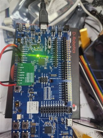
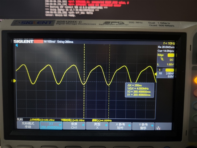
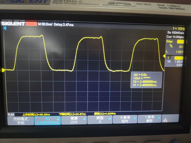
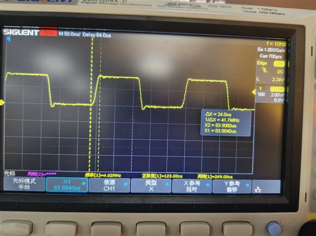
I am using the Nordic nRF5340 DK to communicate with the ICM-42688-P sensor via SPI. However, the sensor does not respond to the MCU's commands. After observing the SPI clock (SCLK) waveform with an oscilloscope. I noticed that the rise and fall times of the clock signal are excessively long, which violates the sensor’s timing requirements.
I configured the SCLK GPIO pin’s drive strength to H0H1 but the issue persists. Following is my code using nrfx driver:
/* configurations in prj.conf
CONFIG_GPIO=y
CONFIG_LOG=y
CONFIG_SPI=y
CONFIG_NRFX_SPIM4=y
*/

#include <zephyr/kernel.h>
#include <zephyr/logging/log.h>
#include <zephyr/device.h>
#include <zephyr/drivers/spi.h>
#include <zephyr/sys/printk.h>

#include <nrf.h>
#include <nrfx_spim.h>
#include <nrfx_gpiote.h>
#include <hal/nrf_gpio.h>

#include <stdio.h>
#include <string.h>

LOG_MODULE_REGISTER(nrf_imu, 4);

nrfx_spim_t spim = NRFX_SPIM_INSTANCE(4);

#define SPI_SCK_PIN   NRF_GPIO_PIN_MAP(1, 15)
#define SPI_MOSI_PIN  NRF_GPIO_PIN_MAP(1, 13)
#define SPI_MISO_PIN  NRF_GPIO_PIN_MAP(1, 14)
#define SPI_CSN_PIN   NRF_GPIO_PIN_MAP(1, 12)

#define NRFX_CUSTOM_ERROR_CODES 0 //used in nrfx_errors.h

nrfx_spim_config_t spim_config = NRFX_SPIM_DEFAULT_CONFIG(SPI_SCK_PIN, SPI_MOSI_PIN, SPI_MISO_PIN, SPI_CSN_PIN);

uint8_t ret = 0x00;

static volatile bool
	spim_xfer_done;

void spim_event_handler(nrfx_spim_evt_t const *p_event, void *p_context)
{
	spim_xfer_done = true;
}

int main(void)
{
    LOG_INF("Hello");
    spim_xfer_done = false;
    spim_config.orc = 0x47;
	nrfx_spim_init(&spim, &spim_config, spim_event_handler, NULL);

    nrf_gpio_cfg(
        SPI_SCK_PIN,
        NRF_GPIO_PIN_DIR_OUTPUT,
        NRF_GPIO_PIN_INPUT_DISCONNECT,
        NRF_GPIO_PIN_NOPULL,
        NRF_GPIO_PIN_H0H1,
        NRF_GPIO_PIN_NOSENSE
    );

    uint8_t tx_buffer[2] = {0x76, 0x00};
    uint8_t rx_buffer[2] = {0x00, 0x00};

    nrfx_spim_xfer_desc_t transfer = NRFX_SPIM_XFER_TX(tx_buffer, sizeof(tx_buffer));
    nrfx_spim_xfer(&spim, &transfer, 0);
    k_usleep(100);

    tx_buffer[0] = 0x11;
    tx_buffer[1] = 0x01;

    nrfx_spim_xfer(&spim, &transfer, 0);
    k_msleep(2);

    tx_buffer[0] = 0xF5;
    tx_buffer[1] = 0x00;

    nrfx_spim_xfer_desc_t tr = NRFX_SPIM_XFER_TRX(tx_buffer, sizeof(tx_buffer), rx_buffer, sizeof(rx_buffer));
    nrfx_spim_xfer(&spim, &tr, 0);

    LOG_INF("received %d %d", rx_buffer[0], rx_buffer[1]);
}
Then I Cross-tested with an nRF51822-based third-party development board, The SPI interface works, with successful communication.
-
Are there additional configurations (e.g., slew rate, pin control settings) to further optimize the GPIO output characteristics on the nRF5340?
-
Could this be related to hardware design limitations (e.g., pull-up/down resistors, trace impedance) on the nRF5340 DK?
-
Are there known workarounds or firmware adjustments to mitigate this issue?