RF Section feedback

Hi,

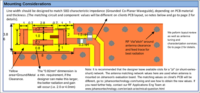
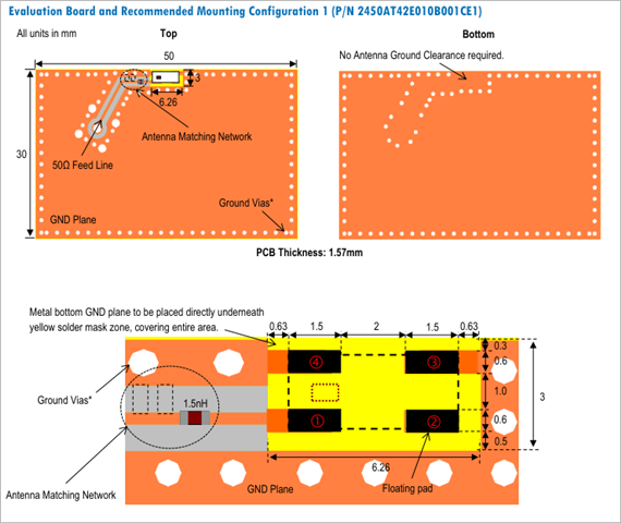
This is my first time designing RF section for BLE using nRF54l15, and i was wondering if you guys can give me some feedback on hardware design. I chose a Johanson 2450AT42B100 chip antenna to save more space as board have strict dimension constraints. I used 0.157mm trace width for 50ohm line. I got this value from pcb supplier. I used matching networks from nRF and anetnna documentation and it looks like this:
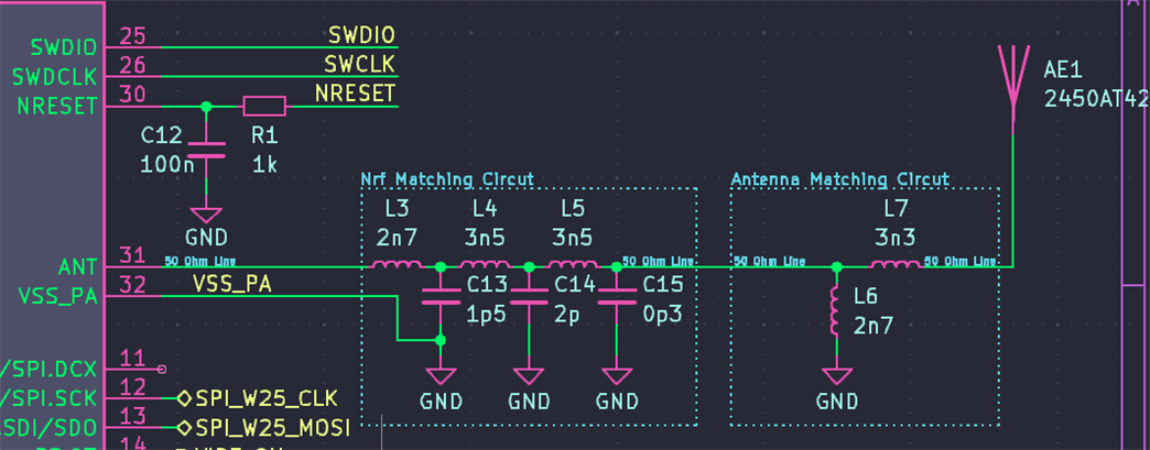
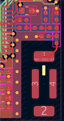
PCB Layout:

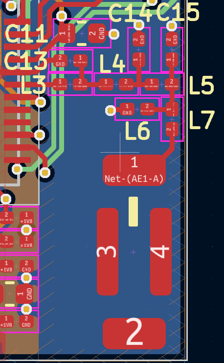
I connected C13 gnd pad to nRF pin 32. Rest of gnd connections are made to bottom layer through vias.

Thank you for your feedback!

Parents
  • Hi,

    Apologies for the delay.

    Schematic wise this looks good, but the layout is far from optimal.

    • There should be ground on either side of the radio matching network on the top layer.
    • No traces can be run directly under the RF path, a internal layer must be used for shielding any traces that needs to be routed under the RF components.
      The traces on the second layer can be moved to the bottom layer, and the ground fill on the 3rd layer extended to under the RF components. If this is done the grounding of C14 must be only connected to the 3rd layer.
    • The antenna is designed to have a 1mm gap to the top layer ground fill:

      It may not perform as expected if the mounting recommendations from the antenna datasheet isn't followed.
      There must also not be any ground under the antenna keepout area, so the bottom layer needs a keepout area.


    Best regards,

    Bendik

Reply
  • Hi,

    Apologies for the delay.

    Schematic wise this looks good, but the layout is far from optimal.

    • There should be ground on either side of the radio matching network on the top layer.
    • No traces can be run directly under the RF path, a internal layer must be used for shielding any traces that needs to be routed under the RF components.
      The traces on the second layer can be moved to the bottom layer, and the ground fill on the 3rd layer extended to under the RF components. If this is done the grounding of C14 must be only connected to the 3rd layer.
    • The antenna is designed to have a 1mm gap to the top layer ground fill:

      It may not perform as expected if the mounting recommendations from the antenna datasheet isn't followed.
      There must also not be any ground under the antenna keepout area, so the bottom layer needs a keepout area.


    Best regards,

    Bendik

Children
Related