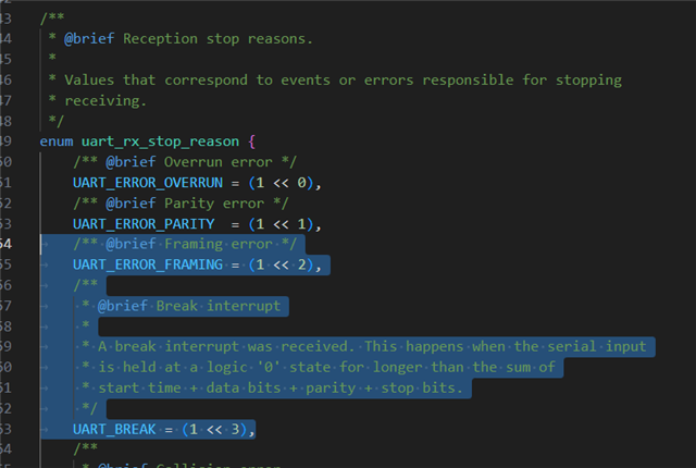
Do we have documentation anywhere detailing which pin is used or not in the 9161 DK and 7002 DK? I see docs like this:
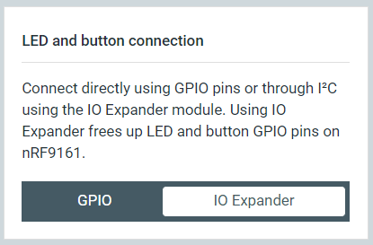
I selected pin 21 thinking it's unused, but I think it's actually set to the value of a button or something else, so I'm unable to use it. I have this set to I/O expander thinking it would at least free up some pins:
However that does not work at all, as some of those pins still hold the value of the buttons/LED states or something else.
The short of it is I'm trying to set up UART1 on this device (9161 DK), and I've got a device tree like so (trying various pins):
&uart3 {
    status = "disabled";
};

&spi3 {
    gd25wb256: gd25wb256e3ir@1 {
        status = "disabled";
    };

    status = "okay";
    pinctrl-0 = <&spi3_default>;
    pinctrl-1 = <&spi3_sleep>;
    pinctrl-names = "default", "sleep";
    cs-gpios = <&gpio0 10 GPIO_ACTIVE_LOW>;

    sdhc0: sdhc@0 {
        compatible = "zephyr,sdhc-spi-slot";
        reg = <0>;
        status = "okay";
        mmc {
            compatible = "zephyr,sdmmc-disk";
            status = "okay";
            label = "SDMMC";
        };
        spi-max-frequency = <25000000>;
    };
};

&pinctrl {
    uart1_default_alt: uart1_default_alt {
        group1 {
            psels = <NRF_PSEL(UART_TX, 0, 26)>,
                <NRF_PSEL(UART_RX, 0, 28)>,
                <NRF_PSEL(UART_RTS, 0, 25)>,
                <NRF_PSEL(UART_CTS, 0, 27)>;
        };
    };

    uart1_sleep_alt: uart1_sleep_alt {
        group1 {
            psels = <NRF_PSEL(UART_TX, 0, 26)>,
                <NRF_PSEL(UART_RX, 0, 28)>,
                <NRF_PSEL(UART_RTS, 0, 25)>,
                <NRF_PSEL(UART_CTS, 0, 27)>;
            low-power-enable;
        };
    };
};

&uart1 {
    status = "okay";
    current-speed = <115200>;
    pinctrl-0 = <&uart1_default_alt>;
    pinctrl-1 = <&uart1_sleep_alt>;
    pinctrl-names = "default", "sleep";
    compatible = "nordic,nrf-uarte";
    hw-flow-control;
};
I am using pins 10-13 for my SD card, pins 30-31 for another peripheral, and those work fine. I've been trying to see what other pins I can use for UART1, tried various pins and I keep getting conflicts.
Is there a comprehensive doc somewhere showing which pins are actually free to use on this board?