
Hello everyone,
I trying to configure my MDBT50Q-U512k to use the ble_app_nus example. According to my board, I need change to uart pins defined in this example. Then, I have problems to configure it. My schematic is:
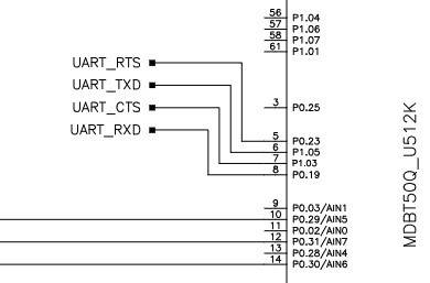
and the defult uart_init funcion is:
static void uart_init(void)
{
    uint32_t                     err_code;
    app_uart_comm_params_t const comm_params =
    {
        .rx_pin_no    = RX_PIN_NUMBER,
        .tx_pin_no    = TX_PIN_NUMBER,
        .rts_pin_no   = RTS_PIN_NUMBER,
        .cts_pin_no   =CTS_PIN_NUMBER,
        .flow_control = APP_UART_FLOW_CONTROL_DISABLED,
        .use_parity   = false,
#if defined (UART_PRESENT)
        .baud_rate    = NRF_UART_BAUDRATE_115200
#else
        .baud_rate    = NRF_UARTE_BAUDRATE_115200
#endif
    };

    APP_UART_FIFO_INIT(&comm_params,
                       UART_RX_BUF_SIZE,
                       UART_TX_BUF_SIZE,
                       uart_event_handle,
                       APP_IRQ_PRIORITY_LOWEST,
                       err_code);
    APP_ERROR_CHECK(err_code);
}
where the default pins are:
#define RX_PIN_NUMBER 8
#define TX_PIN_NUMBER 6
#define CTS_PIN_NUMBER 7
#define RTS_PIN_NUMBER 5
#define HWFC true
but to my code I modified according to my schematic, but the tx pin doesn't work.
static void uart_init(void)
{
    uint32_t                     err_code;
    app_uart_comm_params_t const comm_params =
    {
        .rx_pin_no    = 19,//RX_PIN_NUMBER,
        .tx_pin_no    = 5, //TX_PIN_NUMBER,
        .rts_pin_no   = 23,//RTS_PIN_NUMBER,
        .cts_pin_no   = 3,//CTS_PIN_NUMBER,
        .flow_control = APP_UART_FLOW_CONTROL_DISABLED,
        .use_parity   = false,
#if defined (UART_PRESENT)
        .baud_rate    = NRF_UART_BAUDRATE_115200
#else
        .baud_rate    = NRF_UARTE_BAUDRATE_115200
#endif
    };

    APP_UART_FIFO_INIT(&comm_params,
                       UART_RX_BUF_SIZE,
                       UART_TX_BUF_SIZE,
                       uart_event_handle,
                       APP_IRQ_PRIORITY_LOWEST,
                       err_code);
    APP_ERROR_CHECK(err_code);
}
I developed according to datasheet (see top view pins below)
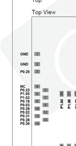
Anyone can help me to solve it? Regards
