I have implemented a program that sends an image's .HEX file through our custom software. The data is received and parsed by an application running on an NRF5340. The relevant portion is extracted and written to the correct partition using flash_img_buffered_write.
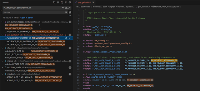
For the application update, I use PM_MCUBOOT_SECONDARY_ID to select the partition where the data is written. This process works well—after writing the received data, the device marks the image as pending using boot_request_upgrade(BOOT_UPGRADE_PERMANENT), then resets. Upon reboot, the image is moved from the secondary partition to the primary partition, and the new firmware starts successfully.
However, when attempting to update the bootloader or network core, it’s unclear which partition ID should be used. Which partition should I write to in order to update these components? Additionally, are there any extra steps or function calls required to properly update either the bootloader or the network core? Lastly, can all three or at least two of them be updated simultaneously using this method?
I have attached the partition file to show the available partitions:
partitions.yml:
EMPTY_0:
  address: 0xfe000
  end_address: 0x100000
  placement:
    after:
    - settings_storage
  region: flash_primary
  size: 0x2000
app:
  address: 0x20200
  end_address: 0xfc000
  region: flash_primary
  size: 0xdbe00
app_image:
  address: 0x20200
  end_address: 0xfc000
  orig_span: &id001
  - app
  region: flash_primary
  size: 0xdbe00
  span: *id001
b0:
  address: 0x0
  end_address: 0x8000
  placement:
    after:
    - start
  region: flash_primary
  size: 0x8000
b0_container:
  address: 0x0
  end_address: 0x8000
  orig_span: &id002
  - b0
  region: flash_primary
  size: 0x8000
  span: *id002
external_flash:
  address: 0x11c000
  end_address: 0x800000
  region: external_flash
  size: 0x6e4000
mcuboot:
  address: 0x8200
  end_address: 0x14000
  placement:
    align:
      end: 0x1000
    before:
    - mcuboot_primary
  region: flash_primary
  sharers: 0x1
  size: 0xbe00
mcuboot_pad:
  address: 0x20000
  end_address: 0x20200
  placement:
    align:
      start: 0x4000
    before:
    - mcuboot_primary_app
  region: flash_primary
  sharers: 0x2
  size: 0x200
mcuboot_primary:
  address: 0x20000
  end_address: 0xfc000
  orig_span: &id003
  - app
  - mcuboot_pad
  region: flash_primary
  size: 0xdc000
  span: *id003
mcuboot_primary_1:
  address: 0x0
  device: nordic_ram_flash_controller
  end_address: 0x40000
  region: ram_flash
  size: 0x40000
mcuboot_primary_app:
  address: 0x20200
  end_address: 0xfc000
  orig_span: &id004
  - app
  region: flash_primary
  size: 0xdbe00
  span: *id004
mcuboot_secondary:
  address: 0x0
  device: DT_CHOSEN(nordic_pm_ext_flash)
  end_address: 0xdc000
  placement:
    align:
      start: 0x4
  region: external_flash
  share_size:
  - mcuboot_primary
  size: 0xdc000
mcuboot_secondary_1:
  address: 0xdc000
  device: DT_CHOSEN(nordic_pm_ext_flash)
  end_address: 0x11c000
  region: external_flash
  size: 0x40000
otp:
  address: 0xff8380
  end_address: 0xff83fc
  region: otp
  size: 0x7c
pcd_sram:
  address: 0x20000000
  end_address: 0x20002000
  placement:
    after:
    - start
  region: sram_primary
  size: 0x2000
provision:
  address: 0xff8100
  end_address: 0xff8380
  region: otp
  size: 0x280
ram_flash:
  address: 0x40000
  end_address: 0x40000
  region: ram_flash
  size: 0x0
rpmsg_nrf53_sram:
  address: 0x20070000
  end_address: 0x20080000
  placement:
    before:
    - end
  region: sram_primary
  size: 0x10000
s0:
  address: 0x8000
  end_address: 0x14000
  orig_span: &id005
  - mcuboot
  - s0_pad
  region: flash_primary
  size: 0xc000
  span: *id005
s0_image:
  address: 0x8200
  end_address: 0x14000
  orig_span: &id006
  - mcuboot
  region: flash_primary
  size: 0xbe00
  span: *id006
s0_pad:
  address: 0x8000
  end_address: 0x8200
  placement:
    after:
    - b0_container
    align:
      start: 0x4000
  region: flash_primary
  share_size:
  - mcuboot_pad
  size: 0x200
s1:
  address: 0x14000
  end_address: 0x20000
  orig_span: &id007
  - s1_pad
  - s1_image
  region: flash_primary
  size: 0xc000
  span: *id007
s1_image:
  address: 0x14200
  end_address: 0x20000
  placement:
    after:
    - s1_pad
    - s0
  region: flash_primary
  share_size:
  - mcuboot
  size: 0xbe00
s1_pad:
  address: 0x14000
  end_address: 0x14200
  placement:
    after:
    - s0
    align:
      start: 0x4000
  region: flash_primary
  share_size:
  - mcuboot_pad
  size: 0x200
settings_storage:
  address: 0xfc000
  end_address: 0xfe000
  placement:
    align:
      start: 0x4000
    before:
    - end
  region: flash_primary
  size: 0x2000
sram_primary:
  address: 0x20002000
  end_address: 0x20070000
  region: sram_primary
  size: 0x6e000
partitions_CPUNET.yml:
app:
  address: 0x1008800
  end_address: 0x1040000
  orig_span: &id001
  - hci_ipc
  region: flash_primary
  size: 0x37800
  span: *id001
b0n:
  address: 0x1000000
  end_address: 0x1008580
  placement:
    after:
    - start
  region: flash_primary
  size: 0x8580
b0n_container:
  address: 0x1000000
  end_address: 0x1008800
  orig_span: &id002
  - b0n
  - provision
  region: flash_primary
  size: 0x8800
  span: *id002
hci_ipc:
  address: 0x1008800
  end_address: 0x1040000
  region: flash_primary
  size: 0x37800
provision:
  address: 0x1008580
  end_address: 0x1008800
  placement:
    after:
    - b0n
  region: flash_primary
  size: 0x280
sram_primary:
  address: 0x21000000
  end_address: 0x21010000
  region: sram_primary
  size: 0x10000