nRF5 SDK System power off MODE wake up issue.

Hi,

I'm working on an application where the system should enter System OFF mode after some button activity and wake up (restart) on a button press or USB connection.

When I flash the application using Segger Embedded Studio, it works as expected. However, when I flash the combined HEX file (containing the bootloader, application, and SoftDevice) generated using the post-build commands, it only wakes up from the button press. If I connect the USB while in System OFF mode, it enters an unknown state where nothing functions.

I compared the HEX files — one read back from the device (flashed via IDE) and the other generated through the post-build commands — and found differences.

Here are the post-build commands I'm using:
call nrfutil settings generate --family NRF52840 --application CenSyn_EEG.hex --application-version 1 --bootloader-version 1 --bl-settings-version 2 bootloader_settings.hex
call mergehex --merge bootloader_settings.hex secure_bootloader.hex --output Combined_bootloader.hex
call mergehex --merge s140_nrf52_7.2.0_softdevice.hex Combined_bootloader.hex --output SD_FBL.hex
call mergehex --merge CenSyn_EEG.hex SD_FBL.hex --output Final_Hex.hex
call nrfutil pkg generate --hw-version 52 --application-version 2 --application CenSyn_EEG.hex --sd-req 0x100 --key-file private.key CenSyn_EEG_DFU.zip


How can I resolve this issue? Any insights would be greatly appreciated.

Regards,
Theja.

Parents
  • Hello Theja,

    If I connect the USB while in System OFF mode, it enters an unknown state where nothing functions.

    Please run 'nrfjprog --readregs' when the chip is in this state to see if the register readout may reveal what state the device is in.

    I compared the HEX files — one read back from the device (flashed via IDE) and the other generated through the post-build commands — and found differences.

    Does the application region in flash contain different data when you check the flash contents after using these two different methods?

    nrfjprog --memrd 0x0 --n 0x1000000 > memory_content.txt

    call nrfutil settings generate --family NRF52840 --application CenSyn_EEG.hex --application-version 1 --bootloader-version 1 --bl-settings-version 2 bootloader_settings.hex
    call mergehex --merge bootloader_settings.hex secure_bootloader.hex --output Combined_bootloader.hex
    call mergehex --merge s140_nrf52_7.2.0_softdevice.hex Combined_bootloader.hex --output SD_FBL.hex
    call mergehex --merge CenSyn_EEG.hex SD_FBL.hex --output Final_Hex.hex
    call nrfutil pkg generate --hw-version 52 --application-version 2 --application CenSyn_EEG.hex --sd-req 0x100 --key-file private.key CenSyn_EEG_DFU.zip

    Is there a flash command that comes after this?

    Thanks,

    Vidar

  • Hi,

    Apologies for the delayed response. I’ve read the registers while the device was in the unknown state, and I’ve attached the data below for your reference.

    R0: 0x00025F40
    R1: 0x2003FFB8
    R2: 0x00000000
    R3: 0x00000000
    R4: 0x200000B8
    R5: 0x00000000
    R6: 0xE000E000
    R7: 0x00000000
    R8: 0x00000000
    R9: 0x00000000
    R10: 0x00000000
    R11: 0x00000000
    R12: 0x2003FF80
    SP: 0x2003FFB8
    LR: 0x0001671D
    PC: 0x00025F40
    xPSR: 0x61000000
    MSP: 0x2003FFB8
    PSP: 0x00000000
    RAZ: 0x00000000
    CFBP: 0x00000000
    APSR: 0x60000000
    EPSR: 0x01000000
    IPSR: 0x00000000


    Also, please note a few changes compared to previous observations. The device tends to enter the unknown state after being connected to USB. This behavior appears to be random and is not specific to the IDE or the hex file — it's occurring in both cases approximately 5 to 6 times out of 10.

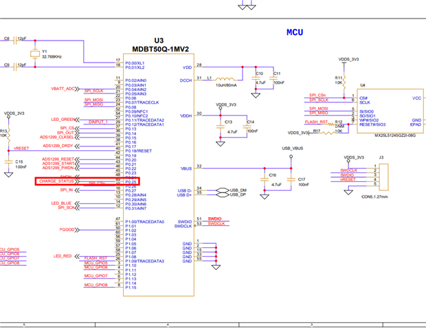
    I’ve also attached the schematic for your reference.POWER_SCH (1).pdf

    To set the GPIO output to 3.3V, I made the following changes. Could this have anything to do with the issue?

        {
            NRF_NVMC->CONFIG = NVMC_CONFIG_WEN_Wen;
            while (NRF_NVMC->READY == NVMC_READY_READY_Busy){}
    
            NRF_UICR->REGOUT0 = (NRF_UICR->REGOUT0 & ~((uint32_t)UICR_REGOUT0_VOUT_Msk)) |
                                (UICR_REGOUT0_VOUT_3V3 << UICR_REGOUT0_VOUT_Pos);  
    
            NRF_NVMC->CONFIG = NVMC_CONFIG_WEN_Ren;
            while (NRF_NVMC->READY == NVMC_READY_READY_Busy){}
        }

  • Hi,

    The readout shows that the program has entered the wait for event loop inside the softdevice which is where a typical application will spent most of its time in. This loop is entered when the application or bootloader calls sd_app_evt_wait(). Are you able to check if the device may be entering bootloader DFU mode after the wake up?

  • Hi, 

    Are you able to check if the device may be entering bootloader DFU mode after the wake up?

    No, after waking up, it enters the application and works as expected.

    To ensure we're on the same page, let me repeat the issue we're facing:

    Using a button action, I put the device into deep sleep (system OFF mode). Before entering deep sleep, I configure the button as a wake-up source.

    The problem is that after entering deep sleep, when I connect the USB, the device wakes up immediately in some cases, but other times it takes over 5 minutes to wake up (the timing varies). Once the device wakes up—even after the delay—it works as expected.

    I’ve attached the deep sleep-related code for your reference.

    void enter_deepSleep()
    {
        ret_code_t  err_code;
        
        nrf_gpio_pin_clear(SHDN);
        nrf_gpio_cfg_input(SHDN, NRF_GPIO_PIN_NOPULL);
    
        nrf_drv_gpiote_in_uninit(BUTTON_PIN_NO);             //UnInitialize the wake-up pin
    
        turn_off_LED(GREEN);
        turn_off_LED(BLUE);
        turn_off_LED(RED);
       
        nrf_drv_gpiote_in_config_t in_config = GPIOTE_CONFIG_IN_SENSE_TOGGLE(false);     //Configure to generate interrupt and wakeup on pin signal low. "false" means that gpiote will use the PORT event, which is low power, i.e. does not add any noticable current consumption (<<1uA). Setting this to "true" will make the gpiote module use GPIOTE->IN events which add ~8uA for nRF52 and ~1mA for nRF51.
        in_config.pull = NRF_GPIO_PIN_PULLUP;                                            //Configure pullup for input pin to prevent it from floting. Pin is pulled down when button is pressed on nRF5x-DK boards, see figure two in http://infocenter.nordicsemi.com/topic/com.nordic.infocenter.nrf52/dita/nrf52/development/dev_kit_v1.1.0/hw_btns_leds.html?cp=2_0_0_1_4
       
        err_code = nrf_drv_gpiote_in_init(BUTTON_PIN_NO, &in_config, NULL);             //Initialize the wake-up pin
        APP_ERROR_CHECK(err_code);                                                       //Check error code returned
        
        nrf_drv_gpiote_in_event_enable(BUTTON_PIN_NO, true);                            //Enable event and interrupt for the wakeup pin   
        
        //StartBlinkTimer(BlinkThrice);
        nrf_delay_ms(2000);
        NRF_POWER->SYSTEMOFF = 1;
    }


    Also, please note that I haven’t done any explicit USB wake-up configuration during deep sleep, as the controller is already connected to USB VBUS.

    regards,
    Theja

Reply
  • Hi, 

    Are you able to check if the device may be entering bootloader DFU mode after the wake up?

    No, after waking up, it enters the application and works as expected.

    To ensure we're on the same page, let me repeat the issue we're facing:

    Using a button action, I put the device into deep sleep (system OFF mode). Before entering deep sleep, I configure the button as a wake-up source.

    The problem is that after entering deep sleep, when I connect the USB, the device wakes up immediately in some cases, but other times it takes over 5 minutes to wake up (the timing varies). Once the device wakes up—even after the delay—it works as expected.

    I’ve attached the deep sleep-related code for your reference.

    void enter_deepSleep()
    {
        ret_code_t  err_code;
        
        nrf_gpio_pin_clear(SHDN);
        nrf_gpio_cfg_input(SHDN, NRF_GPIO_PIN_NOPULL);
    
        nrf_drv_gpiote_in_uninit(BUTTON_PIN_NO);             //UnInitialize the wake-up pin
    
        turn_off_LED(GREEN);
        turn_off_LED(BLUE);
        turn_off_LED(RED);
       
        nrf_drv_gpiote_in_config_t in_config = GPIOTE_CONFIG_IN_SENSE_TOGGLE(false);     //Configure to generate interrupt and wakeup on pin signal low. "false" means that gpiote will use the PORT event, which is low power, i.e. does not add any noticable current consumption (<<1uA). Setting this to "true" will make the gpiote module use GPIOTE->IN events which add ~8uA for nRF52 and ~1mA for nRF51.
        in_config.pull = NRF_GPIO_PIN_PULLUP;                                            //Configure pullup for input pin to prevent it from floting. Pin is pulled down when button is pressed on nRF5x-DK boards, see figure two in http://infocenter.nordicsemi.com/topic/com.nordic.infocenter.nrf52/dita/nrf52/development/dev_kit_v1.1.0/hw_btns_leds.html?cp=2_0_0_1_4
       
        err_code = nrf_drv_gpiote_in_init(BUTTON_PIN_NO, &in_config, NULL);             //Initialize the wake-up pin
        APP_ERROR_CHECK(err_code);                                                       //Check error code returned
        
        nrf_drv_gpiote_in_event_enable(BUTTON_PIN_NO, true);                            //Enable event and interrupt for the wakeup pin   
        
        //StartBlinkTimer(BlinkThrice);
        nrf_delay_ms(2000);
        NRF_POWER->SYSTEMOFF = 1;
    }


    Also, please note that I haven’t done any explicit USB wake-up configuration during deep sleep, as the controller is already connected to USB VBUS.

    regards,
    Theja

Children
Related