
Hi all,
I applied QSPI driver on NCS 2.4.0 with QSPI LCD panel and I encountered the problem.
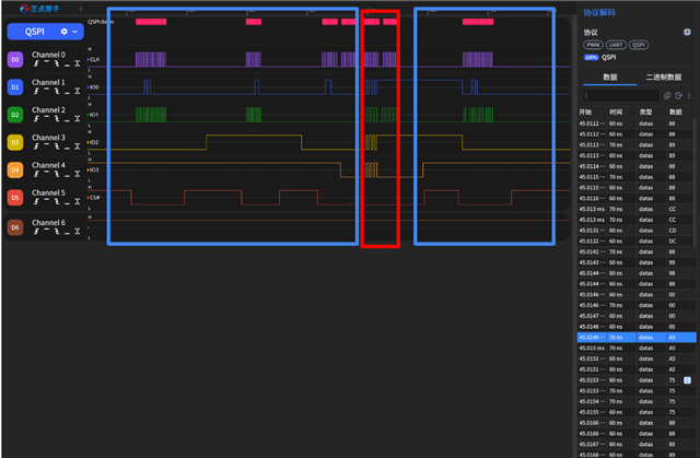
The red area is the data I sent, but the blue area is not what I sent.
I already try many way to send with qspi, like nrfx_qspi_write() or directly write to register NRF_QSPI
but all result are the same.
Is this caused by the hardware design, or can I modify it on the software side?
I already read the post below, but it seems no solution update.
Wayne

