What is the difference between ppib and dppic?

Hello,

I am trying to use the nRF21540 in nRF54L15, I notice document metion

Enable appropriate instances of the DPPIC and PPIB peripherals in the devicetree file:

Explain this code
Copy
Copy&dppic10 {
      status = "okay";
};

&ppib11 {
      status = "okay";
};

&ppib21 {
      status = "okay";
};

&dppic20 {
      status = "okay";
};

&ppib22 {
      status = "okay";
};

&ppib30 {
      status = "okay";
};

&dppic30 {
      status = "okay";
};

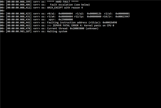
I am wondering what is the difference between PPIB and DPPIC. What does appropriate mean? How to choose the correct one. If I open all the node I will got an fatal error below:

Parents
  • Hello,

    It is all PPI, but it is called a bit different things depending on the context. In general, PPI is what it was called on the nRF52 series. In the nRF5340 it was called DPPI (Distributed Programmable peripheral interface), and you will also see something called GPPI (generic programmable peripheral interface). DPPIC is Distributed programmable peripheral interface controller, and I believe PPIB is PPI Bridge. 

    This, however, doesn't explain what caused your application to crash. Did it print something else in the log before the part that you show in the screenshot? Is it one of our samples that you are running? If so, which one?

    Best regards,

    Edvin

  • Hi,

    I am trying to make nRF21540 available in nRF54L15 DK. 

    As shown in this ticket.

    Thank you for your time!

  • After change to NCS v3.0.0-preview2 there is no error, however, the BLE is not working.

  • I didn't get the same error, but I needed to change the pins, because the ones that you selected aren't routed through to the pin headers on the DK. Al the pins marked with parenthesis, such as P1.00, 01, 02, 03, 04 are by default connected to the external flash chip (you can see it on the back of the DK. Try using this:

    / {
    	nrf_radio_fem: name_of_fem_node {
    	   compatible  = "nordic,nrf21540-fem";
    	   tx-en-gpios = <&gpio1 7 GPIO_ACTIVE_HIGH>;
    	   rx-en-gpios = <&gpio1 5 GPIO_ACTIVE_HIGH>;
    	   pdn-gpios   = <&gpio1 8 GPIO_ACTIVE_HIGH>;
    		mode-gpios   = <&gpio1 4 GPIO_ACTIVE_HIGH>;
    		tx-en-settle-time-us = <12>;
    		rx-en-settle-time-us = <12>;
     };
    }; //54L15

    and connect accordingly. Does that change the behavior?

    My 21-EK doesn't have any antennas connected to it, so I am not sure whether it works.

    If it still fails, please let me know what build command you are using. I tested in both 2.9.0 and v3.0.0-rc1, and it didn't fail in any of them (according to the logs).

    Best regards,

    Edvin

  • I was also just informed that you should use P0, not P1. So try to use gpio1 (none of these are in use by default). There is more delay on the pins for P1 and P2, so perhaps using P0 will solve your issue.

    Best regards,

    Edvin

  • "It is recommended to use the GPIO pins that belong to the PERI Power Domain of the nRF54L device. For example, on the nRF54L15, these are pins belonging to GPIO P1. " in this case I should use GPIO1 rather than GPIO P0 and P2 why 

    should use P0, not P1
    elay on the pins for P1 and P2

    When I use your setting, the problem still happen, you can see when I plug in the SWF connector, the siganl strength reduce.

    Using your setting seems have some problems, the GPIO 1 4and5 is set to be UART1

Reply
  • "It is recommended to use the GPIO pins that belong to the PERI Power Domain of the nRF54L device. For example, on the nRF54L15, these are pins belonging to GPIO P1. " in this case I should use GPIO1 rather than GPIO P0 and P2 why 

    should use P0, not P1
    elay on the pins for P1 and P2

    When I use your setting, the problem still happen, you can see when I plug in the SWF connector, the siganl strength reduce.

    Using your setting seems have some problems, the GPIO 1 4and5 is set to be UART1

Children
No Data
Related