Hello Nordic community,
I'm working on a project using the nRF5340DK where I need to achieve precise control over three GPIOs with the following specifications:
- P0.07: Generate a 1 MHz continuous clock, toggling every 500 ns.
- P0.12 (pulse): Set HIGH for 500 ns on the 1st, 3rd, 5th, etc., rising edges of the P0.07 clock.
- P0.28 (rst_tdc): Set HIGH for 500 ns on the 2nd, 4th, 6th, etc., rising edges of the P0.07 clock.
The sequence is controlled using GPIOTE for toggling, TIMER for timing, and DPPI for coordination, and the operation is triggered by a Bluetooth command "02" from MATLAB.
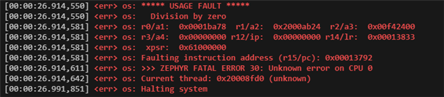
However, when the sequence starts, I encounter a "Division by Zero" error, and the system halts. Here are the error details:
Here is my code:
#include <zephyr/kernel.h>
#include <zephyr/device.h>
#include <zephyr/drivers/gpio.h>
#include <zephyr/bluetooth/bluetooth.h>
#include <zephyr/bluetooth/gatt.h>
#include <zephyr/logging/log.h>
#include <nrfx_gpiote.h>
#include <nrfx_timer.h>
#include <helpers/nrfx_gppi.h>
#include <hal/nrf_gpiote.h>
#include <hal/nrf_timer.h>
#include <hal/nrf_gpio.h>
LOG_MODULE_REGISTER(ble_led_loop, LOG_LEVEL_INF);
#define DEVICE_NAME CONFIG_BT_DEVICE_NAME
#define DEVICE_NAME_LEN (sizeof(DEVICE_NAME) - 1)
// Use NRF_GPIO_PIN_MAP to properly define GPIO pins
#define CLK_GPIO_PIN NRF_GPIO_PIN_MAP(0, 7) // clk_wrd (1 MHz clock)
#define DATA_GPIO_PIN NRF_GPIO_PIN_MAP(0, 12) // Pulse
#define RST_GPIO_PIN NRF_GPIO_PIN_MAP(0, 28) // rst_tdc
#define TIMER_CC_CHANNEL 0
#define GPIOTE_CLK_CH 0
#define GPIOTE_DATA_CH 1
#define GPIOTE_RST_CH 2
static uint8_t command_value[20] = {0};
static bool notify_enabled = false;
static uint8_t gppi_channel_clk;
static volatile uint32_t edge_counter = 0;
// Define instances for GPIOTE
static const nrfx_gpiote_t gpiote = NRFX_GPIOTE_INSTANCE(0);
// Define the timer instance
static const nrfx_timer_t m_timer = NRFX_TIMER_INSTANCE(1);
static ssize_t write_command(struct bt_conn *conn, const struct bt_gatt_attr *attr, const void *buf, uint16_t len, uint16_t offset, uint8_t flags);
static void ccc_cfg_changed(const struct bt_gatt_attr *attr, uint16_t value);
static void run_led_loop2(void);
static void timer_handler(nrf_timer_event_t event_type, void *context);
BT_GATT_SERVICE_DEFINE(my_service,
BT_GATT_PRIMARY_SERVICE(BT_UUID_DECLARE_16(0xFFF0)),
BT_GATT_CHARACTERISTIC(BT_UUID_DECLARE_16(0xFFF1),
BT_GATT_CHRC_WRITE,
BT_GATT_PERM_WRITE,
NULL, write_command, NULL),
BT_GATT_CHARACTERISTIC(BT_UUID_DECLARE_16(0xFFF3),
BT_GATT_CHRC_NOTIFY,
BT_GATT_PERM_NONE,
NULL, NULL, &command_value),
BT_GATT_CCC(ccc_cfg_changed, BT_GATT_PERM_READ | BT_GATT_PERM_WRITE)
);
static const struct bt_data ad[] = {
BT_DATA_BYTES(BT_DATA_FLAGS, (BT_LE_AD_GENERAL | BT_LE_AD_NO_BREDR)),
BT_DATA(BT_DATA_NAME_COMPLETE, DEVICE_NAME, DEVICE_NAME_LEN),
};
static const struct bt_data sd[] = {
BT_DATA_BYTES(BT_DATA_UUID16_ALL, 0xF0),
};
static void timer_handler(nrf_timer_event_t event_type, void *context) {
if (event_type == NRF_TIMER_EVENT_COMPARE0) {
edge_counter++;
if (edge_counter % 2 == 1) {
// Odd counts: Enable pulse, disable rst_tdc
nrf_gpio_pin_set(DATA_GPIO_PIN);
nrf_gpio_pin_clear(RST_GPIO_PIN);
} else {
// Even counts: Disable pulse, enable rst_tdc
nrf_gpio_pin_clear(DATA_GPIO_PIN);
nrf_gpio_pin_set(RST_GPIO_PIN);
}
// Add a delay to ensure the pulse is only 500ns
k_busy_wait(1); // Approximate 500ns delay
// Turn off both signals after 500ns
nrf_gpio_pin_clear(DATA_GPIO_PIN);
nrf_gpio_pin_clear(RST_GPIO_PIN);
}
}
static void ccc_cfg_changed(const struct bt_gatt_attr *attr, uint16_t value) {
notify_enabled = (value == BT_GATT_CCC_NOTIFY);
LOG_INF("Notifications %s", notify_enabled ? "enabled" : "disabled");
}
static ssize_t write_command(struct bt_conn *conn, const struct bt_gatt_attr *attr, const void *buf, uint16_t len, uint16_t offset, uint8_t flags) {
if (len > sizeof(command_value) - 1) {
return BT_GATT_ERR(BT_ATT_ERR_INVALID_OFFSET);
}
memcpy(command_value, buf, len);
command_value[len] = '\0'; // Ensure null termination
LOG_INF("Received Command: %s", command_value);
if (strncmp((char *)command_value, "02", 2) == 0) {
LOG_INF("Starting precise waveform sequence...");
run_led_loop2();
}
return len;
}
static void run_led_loop2(void) {
LOG_INF(" ️ Starting hardware-timed waveform...");
️ Starting hardware-timed waveform..."); nrfx_err_t err;
// Initialize GPIOTE
err = nrfx_gpiote_init(&gpiote, NRFX_GPIOTE_DEFAULT_CONFIG_IRQ_PRIORITY);
if (err != NRFX_SUCCESS) {
LOG_ERR("GPIOTE init failed: %d", err);
return;
}
// Configure GPIO pins as outputs
nrf_gpio_cfg_output(CLK_GPIO_PIN);
nrf_gpio_cfg_output(DATA_GPIO_PIN);
nrf_gpio_cfg_output(RST_GPIO_PIN);
// Set initial pin states
nrf_gpio_pin_clear(CLK_GPIO_PIN);
nrf_gpio_pin_clear(DATA_GPIO_PIN);
nrf_gpio_pin_clear(RST_GPIO_PIN);
// Configure GPIOTE for clock pin toggle
nrf_gpiote_task_configure(NRF_GPIOTE, GPIOTE_CLK_CH, CLK_GPIO_PIN,
NRF_GPIOTE_POLARITY_TOGGLE,
NRF_GPIOTE_INITIAL_VALUE_LOW);
nrf_gpiote_task_enable(NRF_GPIOTE, GPIOTE_CLK_CH);
// Configure timer for 1 MHz clock generation
nrfx_timer_config_t timer_cfg = {
.frequency = NRF_TIMER_FREQ_16MHz,
.mode = NRF_TIMER_MODE_TIMER,
.bit_width = NRF_TIMER_BIT_WIDTH_32,
.interrupt_priority = NRFX_TIMER_DEFAULT_CONFIG_IRQ_PRIORITY,
.p_context = NULL
};
err = nrfx_timer_init(&m_timer, &timer_cfg, timer_handler);
if (err != NRFX_SUCCESS) {
LOG_ERR("Timer init failed: %d", err);
return;
}
// Set CC0 for 1 MHz clock (16MHz / 16 = 1MHz)
nrfx_timer_extended_compare(&m_timer, NRF_TIMER_CC_CHANNEL0, 16,
NRF_TIMER_SHORT_COMPARE0_CLEAR_MASK, true);
// Allocate GPPI channel for clock signal
err = nrfx_gppi_channel_alloc(&gppi_channel_clk);
if (err != NRFX_SUCCESS) {
LOG_ERR("GPPI channel allocation failed: %d", err);
return;
}
// Connect timer event to GPIOTE task for clock signal
uint32_t timer_compare_event = nrfx_timer_event_address_get(&m_timer, NRF_TIMER_EVENT_COMPARE0);
uint32_t gpiote_task = nrf_gpiote_task_address_get(NRF_GPIOTE, NRF_GPIOTE_TASK_OUT_0 + GPIOTE_CLK_CH);
// These are void functions, don't assign their return values
nrfx_gppi_channel_endpoints_setup(gppi_channel_clk, timer_compare_event, gpiote_task);
// Enable GPPI channel - also a void function
nrfx_gppi_channels_enable(BIT(gppi_channel_clk));
// Reset edge counter
edge_counter = 0;
// Start timer
nrfx_timer_enable(&m_timer);
LOG_INF(" Waveform running via GPIOTE+TIMER+GPPI");
Waveform running via GPIOTE+TIMER+GPPI"); if (notify_enabled) {
strcpy((char *)command_value, "TX Done");
bt_gatt_notify(NULL, &my_service.attrs[3], command_value, strlen((char *)command_value));
}
}
int main(void) {
int err = bt_enable(NULL);
if (err) {
LOG_ERR("Bluetooth init failed (err %d)", err);
return 1;
}
LOG_INF("Bluetooth initialized");
err = bt_le_adv_start(BT_LE_ADV_CONN, ad, ARRAY_SIZE(ad), sd, ARRAY_SIZE(sd));
if (err) {
LOG_ERR("Advertising failed (err %d)", err);
return 1;
}
LOG_INF("Advertising started");
return 0;
}
prj.conf:
# Bluetooth essentials
CONFIG_BT=y
CONFIG_BT_PERIPHERAL=y
CONFIG_BT_DEVICE_NAME="nrf5340_ble"
CONFIG_BT_MAX_CONN=1
CONFIG_BT_GATT_CLIENT=y
# Logging
CONFIG_LOG=y
CONFIG_LOG_DEFAULT_LEVEL=3
# Needed for GPIO + TIMER
CONFIG_GPIO=y
CONFIG_NRFX_TIMER1=y
CONFIG_HEAP_MEM_POOL_SIZE=2048
# Enable high frequency clock
CONFIG_CLOCK_CONTROL=y
CONFIG_CLOCK_CONTROL_NRF=y
Devicetree Overlay:
/ {
aliases {
clk = &clkout;
pulse = &pulseout;
rsttdc = &rstout;
};
gpio_outs {
compatible = "gpio-leds";
clkout: clkout {
gpios = <&gpio0 7 GPIO_ACTIVE_HIGH>;
label = "Clock Output";
};
pulseout: pulseout {
gpios = <&gpio0 12 GPIO_ACTIVE_HIGH>;
label = "Pulse Signal";
};
rstout: rstout {
gpios = <&gpio0 28 GPIO_ACTIVE_HIGH>;
label = "Reset TDC";
};
};
};
&gpio0 {
status = "okay";
};
&gpiote {
status = "okay";
};
&timer1 {
status = "okay";
};
Could anyone help point out what might be going wrong or suggest how to correctly configure the TIMER, GPIOTE, and DPPI for this type of operation? Any advice on debugging strategies for this kind of error would also be greatly appreciated.
Thank you!
