Custom board based on nrf5340 CLAA not working after flashing the application

Hi,

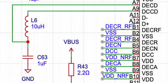
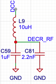
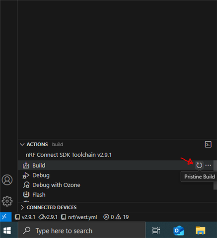
I designed a custom PCB with the nrf5340 CLAA chip and am testing out the board. I want to flash a simple project of lighting up the on-board LED (the LED is connected to P1.07 in my board design). In nrf connect SDK in VS Code, I was able to create a custom board for nrf5340 QKAA (I was told this is fine for CLAA too), add the GPIO pin P1.07 in the DeviceTree, build the project without errors and flash the code to my board via JLink successfully. However, the LED is not lighted up. When I tried to debug, the process always stops at the step “Starting target CPU…” and won’t let me proceed.

I also tried to control the LED directly using JLink.exe via command line (I am using a windows machine because I encountered more issues on mac). I could connect to the chip in JLink. However, I was not able to write the values directly to the registers to light up the LED either. I wrote the values but when I checked the memory at the address, it was still 0. I checked the soldering of my board physically and they are all connected. I measured RESET and Power and they are both around 3.3V. Is there anything that you think I should try to solve this issue? Is there anything specific I should do to flash the code for the first time? (E.g. the chip is initially locked/protected so we can’t write to its memory directly for the first time?) Any advice would be appreciated. Thanks!

  • Hi

    You say you think you have the inductors connected to pin A9 and B6, but I don't see the inductors in your schematics nor in your gerber files, so please make sure whether they're there physically or not. If they're not, you should test on a fresh (unused) nRF5340 custom board since booting with DCDC might put it in an unrecoverable state. 

    Have you tried running your application code on an nRF5340 DK and see if it works on the DK, as that's generally a good way to narrow down whether the issue is in HW or SW.

    Best regards,

    Simon

  • Hi Simon,

    Thanks for your reply. I followed the recommended decoupling for nRF5340 CLAA chip, Config 2, when I designed the board. Are the two 10uH inductors L6 and L9 not related to the usage of internal APP and NET DCDC regulators? I am not an expert in PCB design so please correct me if I am wrong.

    Also, I did take a fresh custom board and disable all regulators in the first flash but unfortunately the board also did not execute the code. Can you see anything wrong with my build and flash log?

    I do not have a nRF5340 DK but I have a Raytac MDBT53V-DB-40. Does it also make sense to test the application on it?

    Thank you very much for your help!

  • Hi

    These inductors were not part of the schematics you uploaded for our review, so it was assumed they were not present. Either way, thank you for confirming it's not the DCDC inductors causing this. It should be fine to test the application for the MDBT53V-DB-40 as long as you make sure you use the board files for this board when building the application. There are no obvious issues with the build/flash log. Make sure you're doing a Pristine build when you build with the DCDC regulators disabled to make sure you overwrite the existing application.

    Best regards,

    Simon

  • Hi Simon,

    I am now able to enter the main function as shown below in debugging by setting CONFIG_CLOCK_CONTROL_NRF_K32SRC_RC=y and 

    # CONFIG_SOC_ENABLE_LFXO is not set because my board does not have an external 32kHz crystal. 
    #include <stdio.h>
    #include <zephyr/kernel.h>
    #include <zephyr/drivers/gpio.h>
    
    /* 1000 msec = 1 sec */
    // #define SLEEP_TIME_MS   1000
    
    /* The devicetree node identifier for the "led0" alias. */
    #define LED0_NODE DT_ALIAS(led0)
    
    /*
     * A build error on this line means your board is unsupported.
     * See the sample documentation for information on how to fix this.
     */
    static const struct gpio_dt_spec led = GPIO_DT_SPEC_GET(LED0_NODE, gpios);
    
    int main(void) {
        if (!device_is_ready(led.port)) {
            return 0;
        }
        gpio_pin_configure_dt(&led, GPIO_OUTPUT_ACTIVE);
        
        while (1) {  // Add infinite loop
            gpio_pin_set_dt(&led, 1);
            k_sleep(K_MSEC(1000));
            gpio_pin_set_dt(&led, 0);
            k_sleep(K_MSEC(1000));
        }
        
        return 0;
    }
    Now after building the application, when I debug, the process stops at the following lines of code in cmsis_gcc_m.h. When I hit continue, the on-board LED starts blinking as expected. However, when I just flash the same code instead of debugging, the code is not executed on the board. Do you have any idea why? Thanks!

    /**
      \brief   Disable IRQ Interrupts
      \details Disables IRQ interrupts by setting special-purpose register PRIMASK.
               Can only be executed in Privileged modes.
     */
    __STATIC_FORCEINLINE void __disable_irq(void)
    {
      __ASM volatile ("cpsid i" : : : "memory");
    }

    Best,
    Ke
  • Hi

    Does your custom board have a 32MHz crystal onboard? If not, that might be why you're only able to see it when a debugger is connected, as in that case the custom board may source the 32MHz crystal from the DK.

    If you do have the 32MHz crystal on your custom board, please double check that it is mounted correctly on the custom board, as a common mistake is that it is mounted 45 degrees off.

    Best regards,

    Simon

Related