nRF54L15 power domains effect on current consumption

Hi,

I'm developing an application on the nRF54L15 and recently I designed a custom PCB with a sensor that gives interrupts when its FIFO is full (should be around every 800ms) and the communication with the sensor uses TWI/I2C. At the time, I wasn't aware of the limitation of not being able to have an interrupt on GPIO2 and I wasn't very familiar with the power domains for the different GPIO ports, and I ended up connecting both the interrupt pin and the TWI pins to GPIO2. I know I will have to do a redesign to maximally make use of the most efficient settings, but I want to learn as much as possible from the current design before updating the design, so I wanted to confirm something.

To circumvent the interrupt issue, I just implement a polling method with a k_sleep(M_SEC(800)). Having only that, with the firmware checking the state of the interrupt pin, the current consumption is pretty much exactly what I expect. However, when I start actually reading the samples from the sensor using the TWI, that's when the current consumption starts showing weird patterns that don't align with my expectations. I'm wondering if this is related to TWI peripheral being in the MCU domain (as opposed to the low-power/peripheral domain.

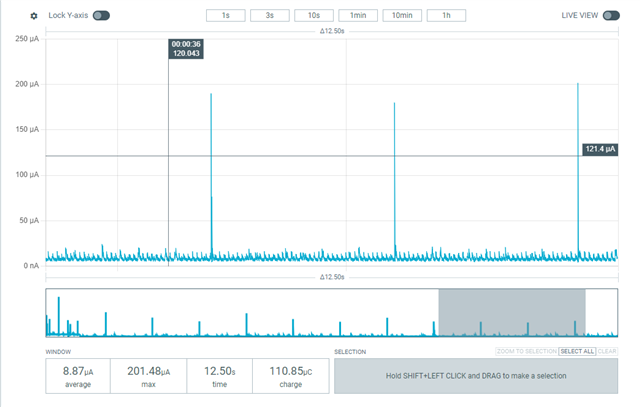
For reference, this is the current consumption of only the sensor running and the polling happening every 800ms.

This is the exact same code, but with the i2c_read functions enabled (nothing else happens after reading the data for now)

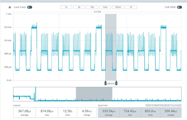
As you can see, the interval between sharp increases is 800ms, which is exactly the interval we're using to read out the device. My feeling is that initiating the i2c_read starts up the MCU domain, which runs for some time and then stops, to then all start again 800ms later. Is that a correct assumption of what could be happening?

But then the question also remains why the baseline current consumption is so much higher for the case where the I2C reads are happening.

For now, I don't have the BLE enabled, but I plan to use it to stream the data every time it comes in (800ms). I assume using BLE will be part of the MCU domain, but I hope it will be possible to get the current consumption to be lower. For reference, I was able to use the nRF52 to get everything working with an average current consumption <100µA (sensor running, reading data over I2C and streaming all data). Would doing as much as possible with peripherals in the low-power domain be my best bet on getting the lowest possible current consumption, or do you believe somethign else could be causing this high current consumption?

Parents
  • Hello,

    Indeed, your second PPK screenshot looks a bit unexpected. I can't tell, only by looking at this, what's going on. But for one, you have a base-current of approximately 200µA, which seems a bit high. 

    Is it possible to zip and send the application that you are currently testing? And feel free to specify where the change you did is located, so that I can easily switch between the two. 

    I don't suppose you are able to reproduce these graphs on an nRF54L15 DK without the actual sensor attached? 

    Please note that we have a public holiday here in Norway, so please expect some delay in our replies. We will be back with normal staffing on Tuesday next week.

    Best regards,

    Edvin

  • Hi Edvin,

    I finally got to doing some more tests on this, and I couldn't get things to work on the nRF54L15 DK. Upon reviewing the datasheet I noticed that the TWI/I2C doesn't seem to be available on P2, and unfortunately, that's where I have my pins routed. On the nRF54L15 DK (v0.9.1) there is no I2C traffic at all on the same P2 pins that I have on the PCB. The weird thing is that if I test my custom PCB, I actually do get data from the sensor, but it seems to only happen when I connect my JLINK for logging over RTT. Very strange, but I'll need to reconfirm if this is actually happening.

Reply
  • Hi Edvin,

    I finally got to doing some more tests on this, and I couldn't get things to work on the nRF54L15 DK. Upon reviewing the datasheet I noticed that the TWI/I2C doesn't seem to be available on P2, and unfortunately, that's where I have my pins routed. On the nRF54L15 DK (v0.9.1) there is no I2C traffic at all on the same P2 pins that I have on the PCB. The weird thing is that if I test my custom PCB, I actually do get data from the sensor, but it seems to only happen when I connect my JLINK for logging over RTT. Very strange, but I'll need to reconfirm if this is actually happening.

Children
  • Hello,

    It is correct that it used to say, in a previous version of the datasheet, that you could use dedicated pins on P2 for TWIM20-22, but that was a documentation bug. In addition, it never said what these dedicated pins were, like it does for the other peripherals working on dedicated pins on P2, such as SPIM00:

    (source: https://docs.nordicsemi.com/bundle/ps_nrf54L15/page/chapters/pin.html#ariaid-title4)

    WoutWG said:
    The weird thing is that if I test my custom PCB, I actually do get data from the sensor, but it seems to only happen when I connect my JLINK for logging over RTT

    It may be, if your PCB has an older revision of the nRF54l15, that the behavior was a bit different. Enabling the RTT viewer will actually put the chip in debug mode, so it will change the clock behavior on the chip. However, officially, TWI is not supported on P2, so even if it works under some conditions on some revisions of the chip (in this case, debug mode), you should not use the for production.

    Best regards,

    Edvin

Related