nRF52810 board will not start on its own. It needs the RTT Viewer to be connected, then it will start and run. It has run on its own before with this configuration:
CONFIG_CLOCK_CONTROL_NRF_K32SRC_RC=y
CONFIG_CLOCK_CONTROL_NRF_K32SRC_XTAL=y
CONFIG_SEGGER_RTT_MODE_NO_BLOCK_SKIP=n
Does anyone have any idea? I have struggled with this for a week now.
PS:
PS:
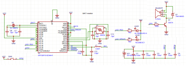
My schematic follows the reference schematics in the datasheet, which means the RESET line is floating. I am convinced this is not an issue because I have another board from Holyiot (beacon) with also floating reset. This board starts and run on its own just fine using the same firmware (pin assignments re-mapped, of course).
Regards,
Regards,