
Hello,
I am trying to get a custom board working with NOR Flash chip but I am having issues getting the flash chip "ready". I am running the sample application "spi-flash" and program fails immediately when it checks if the device is ready.
Are there some limitations when working with certain GPIO pins on the NRF module? Is there anything glaringly wrong with my configuration? I'm lost on what to try next.
I am using the Fanstel module BM15 with a Winbond W25Q64 NOR Flash chip. The relevant device tree information is:
&spi00 {
	status = "okay";
	cs-gpios = <&gpio2 0 GPIO_ACTIVE_LOW>;
	pinctrl-0 = <&spi00_default>;
	pinctrl-names = "default";

	w25q64: w25q64@0 {
		status = "okay";
		compatible = "jedec,spi-nor";
		reg = <0>;
		spi-max-frequency = <8000000>;
		jedec-id = [EF 40 17];  // W25Q64JV
		size = <8388608>;  // 8MB (64Mb)
		has-dpd;
		t-enter-dpd = <10000>;
		t-exit-dpd = <35000>;
	};
};
The flash chip has this pinout:
CS - P2.00
CLK - P1.02
SDI - P1.01
SDO - P1.00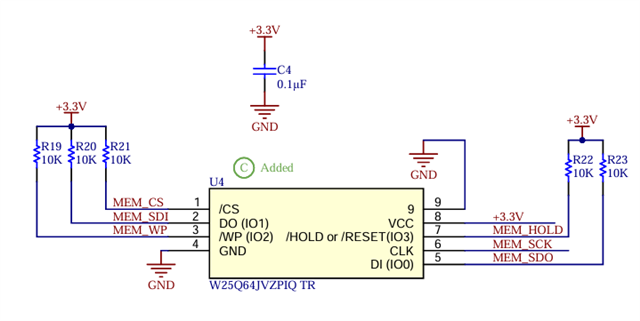
Here is my relevant pin control file:
	spi00_default: spi00_default {
		group1 {
			psels = <NRF_PSEL(SPIM_SCK, 1, 2)>,
				<NRF_PSEL(SPIM_MOSI, 1, 1)>,
				<NRF_PSEL(SPIM_MISO, 1, 0)>;
		};
	};
Here is my devices .defconfig file:
# Copyright (c) 2024 Nordic Semiconductor ASA
# SPDX-License-Identifier: Apache-2.0

# Enable UART driver
CONFIG_SERIAL=y

# Enable console
CONFIG_CONSOLE=y
CONFIG_UART_CONSOLE=y

# Enable GPIO
CONFIG_GPIO=y

# Enable MPU
CONFIG_ARM_MPU=y

# Enable hardware stack protection
CONFIG_HW_STACK_PROTECTION=y

# MPU-based null-pointer dereferencing detection cannot
# be applied as the (0x0 - 0x400) is unmapped for this target.
CONFIG_NULL_POINTER_EXCEPTION_DETECTION_NONE=y

# Enable Cache
CONFIG_CACHE_MANAGEMENT=y
CONFIG_EXTERNAL_CACHE=y

# Start SYSCOUNTER on driver init
CONFIG_NRF_GRTC_START_SYSCOUNTER=y

CONFIG_CLOCK_CONTROL_NRF_K32SRC_RC=y
CONFIG_CLOCK_CONTROL_NRF_K32SRC_XTAL=n


CONFIG_LED=y
CONFIG_PWM=y
CONFIG_LED_PWM=y

CONFIG_NFCT_PINS_AS_GPIOS=y

