GPIO9 & 10 won't operate independently using zephyr (but OK with rRF5 SDK)

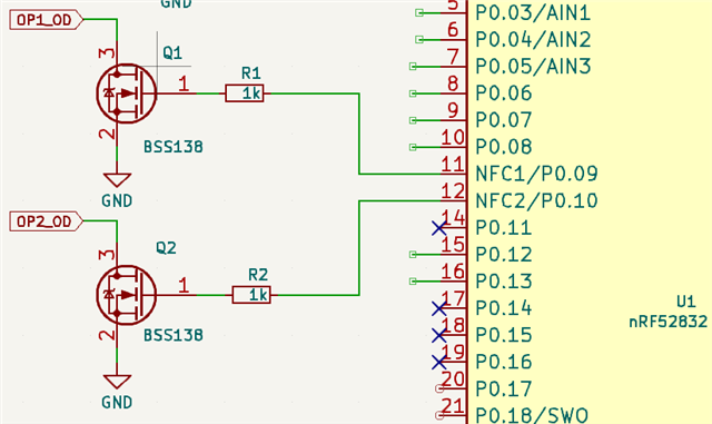
I have a custom nRF52832 board with outputs on P0.07 P0.08 P0.09 P0.10 and I want to write to them. 7&8 are working ok but 9&10 are not.

Let me emphasise THE BOARD IS WORKING FINE. I have applications written using the old nRF5 SDK which I can flash and work no problem, but now I am trying to use nRF Connect SDK.

After some time messing I find out the NFC needs to be disabled, so I have added the line "CONFIG_NFCT_PINS_AS_GPIOS=y" to prj.conf. Now I can write to GPIO pins 9 or 10, but for whatever reason they act as if they are shorted together. i.e. if I set PIN to either 9 or 10 in the test code below then both pins toggle together.

Here is some test code. I was initially using devicetree, but I've simplified it down to the most basic form to get to the bottom of this. I'm guessing this is down to the NFC protection circuitry but can't find any reference to it (I would expect CONFIG_NFCT_PINS_AS_GPIOS=y to disable the protection anyway)

#include <stdio.h>
#include <zephyr/kernel.h>
#include <hal/nrf_gpio.h>>

#define RUN_LED_BLINK_INTERVAL 300
#define PIN 8

int main(void)
{
nrf_gpio_cfg_output(PIN);
for (;;) {
nrf_gpio_pin_set(PIN);
k_sleep(K_MSEC(RUN_LED_BLINK_INTERVAL));
nrf_gpio_pin_clear(PIN);
k_sleep(K_MSEC(RUN_LED_BLINK_INTERVAL));
}
return 0;
}

prj.conf

CONFIG_GPIO=y
CONFIG_DK_LIBRARY=n
CONFIG_NFCT_PINS_AS_GPIOS=y

Parents
  • Hi,


    Are you using a newer version of NCS?

    If yes, then the NFC pin configuration is moved to device tree. Try adding this to your overlay and see if the GPIOs now works as expected:

    &uicr {
    	nfct-pins-as-gpios;
    };


    Kind regards,

    Håkon

  • No that doesn't seem to have fixed it Disappointed

    Maybe there is something wrong with my dts file?

    Here is the code I am using to test now using dts this time; all I am doing is changing line#9 with led0 led1 led2 led3

    #include <stdio.h>
    #include <zephyr/kernel.h>
    #include <zephyr/drivers/gpio.h>
    #include <hal/nrf_gpio.h>
    
    #define GPIO_NODE  DT_NODELABEL(gpio0)
    #define GPIO_NAME	DEVICE_DT_NAME(GPIO_NODE)
    #define RUN_LED_BLINK_INTERVAL 300
    #define OD2_NODE DT_NODELABEL(led2)
    
    int main(void)
    {
    	static const struct gpio_dt_spec od2_spec = GPIO_DT_SPEC_GET(OD2_NODE, gpios);
    	gpio_pin_configure_dt(&od2_spec, GPIO_OUTPUT); 
        printk("Hello\n");
    	for (;;) {
    		gpio_pin_set_dt(&od2_spec, 1);
    		k_sleep(K_MSEC(RUN_LED_BLINK_INTERVAL));
    		gpio_pin_set_dt(&od2_spec, 0);
    		k_sleep(K_MSEC(RUN_LED_BLINK_INTERVAL));
    	}
    		return 0;
    }
    

    /dts-v1/;
    #include <nordic/nrf52832_qfaa.dtsi>
    #include "lptb-pinctrl.dtsi"
    #include <zephyr/dt-bindings/input/input-event-codes.h>
    
    
    / {
    	model = "Custom Board auto generated by nRF Connect for VS Code";
    	compatible = "react,lptb";
    
    	chosen {
    		zephyr,sram = &sram0;
    		zephyr,flash = &flash0;
    		zephyr,code-partition = &slot0_partition;
    		zephyr,console =  &uart0 ;
    		zephyr,shell-uart =  &uart0 ;
    		zephyr,uart-mcumgr = &uart0;
    	};
    	leds {
    		compatible = "gpio-leds";
    		led0: led_0 {
    			gpios = <&gpio0 7 GPIO_ACTIVE_HIGH>;
    			label = "Green LED 0";
    		};
    		led1: led_1 {
    			gpios = <&gpio0 8 GPIO_ACTIVE_HIGH>;
    			label = "Green LED 1";
    		};
    		led2: led_2 {
    			gpios = <&gpio0 9 GPIO_ACTIVE_HIGH>;
    			label = "Green LED 2";
    		};
    		led3: led_3 {
    			gpios = <&gpio0 10 GPIO_ACTIVE_HIGH>;
    			label = "Green LED 3";
    		};
    	};
    	
     
    	buttons {
    		compatible = "gpio-keys";
    		button0: button_0 {
    			gpios = <&gpio0 17 (GPIO_PULL_UP | GPIO_ACTIVE_LOW)>;
    			label = "Push button switch 0";
    			zephyr,code = <INPUT_KEY_0>;
    		};
    		button1: button_1 {
    			gpios = <&gpio0 18 (GPIO_PULL_UP | GPIO_ACTIVE_LOW)>;
    			label = "Push button switch 1";
    			zephyr,code = <INPUT_KEY_1>;
    		};
    		button2: button_2 {
    			gpios = <&gpio0 19 (GPIO_PULL_UP | GPIO_ACTIVE_LOW)>;
    			label = "Push button switch 2";
    			zephyr,code = <INPUT_KEY_2>;
    		};
    		button3: button_3 {
    			gpios = <&gpio0 20 (GPIO_PULL_UP | GPIO_ACTIVE_LOW)>;
    			label = "Push button switch 3";
    			zephyr,code = <INPUT_KEY_3>;
    		};
    	};


    	/* These aliases are provided for compatibility with samples */
    	aliases {
    		led0 = &led0;
    		led1 = &led1;
    		led2 = &led2;
    		led3 = &led3;
    		sw0 = &button0;
    		sw1 = &button1;
    		sw2 = &button2;
    		sw3 = &button3;
    		bootloader-led0 = &led0;
    		mcuboot-button0 = &button0;
    		mcuboot-led0 = &led0;
    		watchdog0 = &wdt0;	
    	};
    };
    
    &flash0 {
    	partitions {
    		compatible = "fixed-partitions";
    		#address-cells = <1>;
    		#size-cells = <1>;
    
    		boot_partition: partition@0 {
    			label = "mcuboot";
    			reg = <0x00000000 DT_SIZE_K(48)>;
    		};
    
    		slot0_partition: partition@c000 {
    			label = "image-0";
    			reg = <0x0000c000 DT_SIZE_K(220)>;
    		};
    
    		slot1_partition: partition@43000 {
    			label = "image-1";
    			reg = <0x00043000 DT_SIZE_K(220)>;
    		};
    
    		storage_partition: partition@7a000 {
    			label = "storage";
    			reg = <0x0007a000 DT_SIZE_K(24)>;
    		};
    	};
    };
    
    &gpiote {
    	status = "okay";
    };
    
    &gpio0 {
    	status = "okay";
    };
    
    &uart0 {
    	compatible = "nordic,nrf-uarte";
    	status = "okay";
    	current-speed = <115200>;
    	pinctrl-0 = <&uart0_default>;
    	pinctrl-1 = <&uart0_sleep>;
    	pinctrl-names = "default", "sleep";
    };
    
    &i2c0 {
    	compatible = "nordic,nrf-twi";
    	status = "okay";
    	pinctrl-0 = <&i2c0_default>;
    	pinctrl-1 = <&i2c0_sleep>;
    	pinctrl-names = "default", "sleep";
    }; 
    
    &uicr {
    	status = "okay";
    	nfct-pins-as-gpios;
    };
    

    Edit: Sorry, forgot to say this is using NCS 2.9.0

  • Hi,


    I might have misread your initial post. When you state that this works in nRF5 SDK, do you mean the GPIOs themselves, ie. P0.09/P0.10?

    Have you modified the nRF52-DK as described here to re-route the NFC interface?

    https://docs.nordicsemi.com/bundle/ug_nrf52832_dk/page/UG/dk/hw_nfc_if.html#d37e110


    Kind regards,

    Håkon

Reply Children
Related