
Hi there,
I built a battery powered custom PCBA with the NRF54L15 and the nPM1300. All the configuration and register work via I2C seems to be working properly (reading V_BAT, T_NTC, controlling LED2 and LDSW via host). I'm currently running the PCBA on a PPK2 to evaluate current consumption. On normal run the system takes 700uA when shipmode is grounded (only 50k internal pullup) by wake sensor and 470uA, when wake sensor is not triggering. Not the best results, but for the first shot ok.
When the nPM enters shipmode (via I2C), the current consumption only falls to 35uA (not the expected 350nA). I checked the measurement with the nPM1300-ek, which gave me correct measurement values of about 350nA in ship mode (with some spikes every 2s).
Now, I do not know, what I am doing wrong. Here are the last commands via I2C when entering ship mode (taken by an oscilloscope on the I2C lines):
Packet;Start Time;End Time;Address Bits;Address;Address + R/W;R/W;Address ACK;Data;Data ACK
1;-1,04983682155295E-05;0,000419069619635458;7;6B;D6;Write;0;08 00 01;0 0 0
2;0,000456957618563912;0,000799485608876558;7;6B;D6;Write;0;08 04;0 0
3;0,000799485608876558;0,00101913360266449;7;6B;D7;Read;0;10;1
4;0,00893004537892862;0,00935910136679409;7;6B;D6;Write;0;08 01 01;0 0 0
5;0,00939391736580942;0,00973593335613655;7;6B;D6;Write;0;08 04;0 0
6;0,00973593335613655;0,00995506934993896;7;6B;D7;Read;0;00;1
7;0,0100252133479552;0,0103682533382533;7;6B;D6;Write;0;05 11;0 0
8;0,0103682533382533;0,0105879013320412;7;6B;D7;Read;0;9B;1
9;0,0106216933310855;0,0109631973214272;7;6B;D6;Write;0;05 12;0 0
10;0,0109631973214272;0,0111828453152151;7;6B;D7;Read;0;E9;1
11;0,0112591333130575;0,011688189300923;7;6B;D6;Write;0;05 00 01;0 0 0
12;0,0117240292999094;0,0121530852877748;7;6B;D6;Write;0;05 01 01;0 0 0
13;0,0123619812818668;0,0127910372697323;7;6B;D6;Write;0;0B 02 01;0 0 0
In short, in the end there's a write of three bytes: 0B 02 01 (2bytes TASKENTERSHIPMODE, 1 byte TRIGGER)
The behavior changes like expected (VDD discharges slowly), but consumptions stays to high.
Additionally here's a small cutout from the schematic (don't want to disclose too much details):
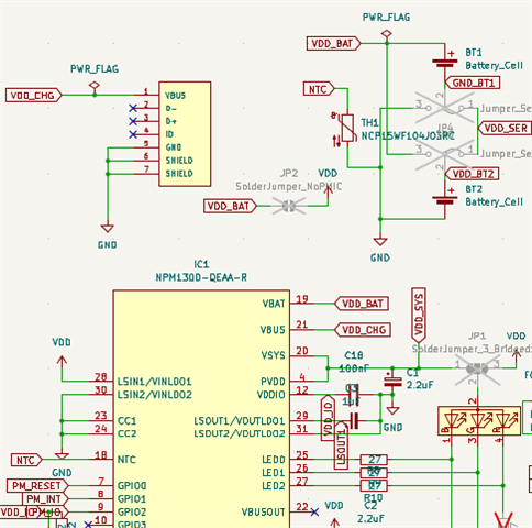
The 2 coin-cell batteries (or in this case the PPM2) are only connected to the VBAT (VDD_BAT net in the schematic). No capacitor, resistor or any other componets are connected.
I really cannot figure out, what the issue could be. Am I missing some configuration?


