I'm using these devices for a personal project, I'm an experienced software engineer but relatively new to MCUs, I know this is a legacy product from Nordic's standpoint but still wanted to ask questions here since there's likely more expertise here than anywhere else.
I've been writing my own library in C on STM32 F4 Nucleo boards and recently got a master/slave working well, I'm an experienced developer not new to C by any means.
However I began to make changes to exploit the ESB auto ack capability and although I got the master to send and the slave to receive, the master never receives any acks and eventually gets an interrupt where the status indicates max retries were reached.
Since my code is unfamiliar to people here and since it's often a struggle to discuss code with issues like this, I added an NRF register dump capability to my library.
My goal here is not to discuss software per-se but discuss the devices register settings, if these are set correctly and people here see no issues with the register setup then the misbehaving acks must be due to either a bogus clone chip or some unusual hardware issue. I'm hoping that the setup is the problem but there are so many anecdotal stories about this device that it's hard to define exactly the correct settings are.
The stuff I've read about pipes, defaults and so on are bewildering and I must have read a hundred posts about this problem.
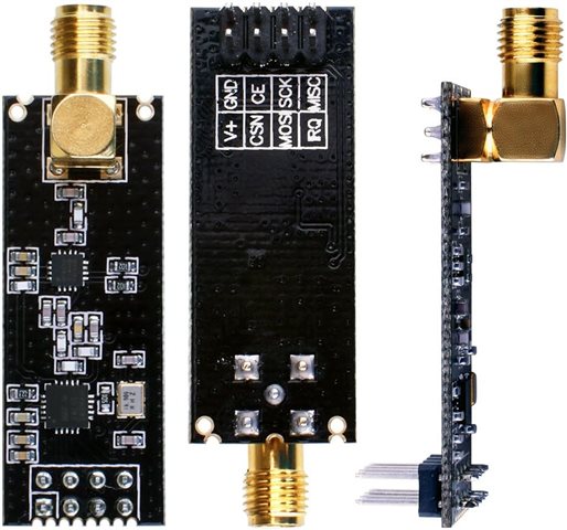
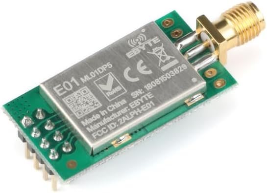
FYI this is the device I'm using, purchased a few years ago and just sitting in my workshop.
This is the Nucleo board - an F446RE board.
I develop using Visual Studio with the VisualGDB product installed.
I'll be posting here later with the dump of the master and slave device registers, hopefully someone will spot a problem in the settings that explains the apparent absence of acks.
FYI the register dump lists the register and their sub-fields in exactly the same order they appear in in the NRF documentation.
OK I have removed my auto-ack settings code, so we can discuss this just by looking at registers that are known to be correctly working without auto-ack, this is the master and slave device's settings and this is from a test app that works but doesn't try to use auto-ack. The dump of the master is taken right before it does a send payload and the dump of the slave is taken right before it enters a wait for interrupt loop.
These settings work, the master flashes the onboard Nucleo LED after if gets the data sent interrupt and the slave flashes the LED when it gets the data received interrupt and this runs fine for hours and the LEDs behave as expected.
this is the master's register setup it just sends fixed length (8 bytes) packets in a loop:
NRF REGISTER DUMP
 CONFIG
  RESERVED    = 0
  MASK_RX_DR  = 0
  MASK_TX_DS  = 0
  MASK_MAX_RT = 0
  EN_CRC      = 0
  CRCO        = 0
  PWR_UP      = 1
  PRIM_RX     = 0

 EN_AA
  RESERVED    = 0
  ENAA_P5     = 0
  ENAA_P4     = 0
  ENAA_P3     = 0
  ENAA_P2     = 0
  ENAA_P1     = 0
  ENAA_P0     = 0

 EN_RXADDR
  RESERVED    = 0
  ERX_P5      = 0
  ERX_P4      = 0
  ERX_P3      = 0
  ERX_P2      = 0
  ERX_P1      = 0
  ERX_P0      = 0

 SETUP_AW
  RESERVED    = 0
  AW          = 3

 SETUP_RETR
  ARD         = 0
  ARC         = 0

 RF_CH
  RESERVED    = 0
  RF_CH       = 45

 RF_SETUP
  CONT_WAVE   = 0
  RESERVED    = 0
  RF_DR_LOW   = 0
  PLL_LOCK    = 0
  RF_DR_HIGH  = 0
  RF_PWR      = 2
  OBSOLETE    = 0

 STATUS
  RESERVED    = 0
  RX_DR       = 0
  TX_DS       = 0
  MAX_RT      = 0
  RX_P_NO     = 7
  TX_FULL     = 0

 OBSERVE_TX
  PLOS_CNT    = 0
  ARC_CNT     = 0

 RPD
  RESERVED    = 0
  RPD         = 0

 RX_ADDR_P0   = E7 E7 E7 E7 E7
 RX_ADDR_P1   = C2 C2 C2 C2 C2
 RX_ADDR_P2   = C3
 RX_ADDR_P3   = C4
 RX_ADDR_P4   = C5
 RX_ADDR_P5   = C6

 TX_ADDR      = 19 51 38 31 00

 RX_PW_0
  RESERVED    = 0
  RX_PW_P0    = 0

 RX_PW_1
  RESERVED    = 0
  RX_PW_P1    = 0

 RX_PW_2
  RESERVED    = 0
  RX_PW_P2    = 0

 RX_PW_3
  RESERVED    = 0
  RX_PW_P3    = 0

 RX_PW_4
  RESERVED    = 0
  RX_PW_P4    = 0

 RX_PW_5
  RESERVED    = 0
  RX_PW_P5    = 0

 FIFO_STATUS
  RESERVED    = 0
  TX_REUSE    = 0
  TX_FULL     = 0
  TX_EMPTY    = 1
  RESERVED    = 0
  RX_FULL     = 0
  RX_EMPTY    = 1

 DYNPD
  RESERVED    = 0
  DPL_P5      = 0
  DPL_P4      = 0
  DPL_P3      = 0
  DPL_P2      = 0
  DPL_P1      = 0
  DPL_P0      = 0

 FEATURE
  RESERVED    = 0
  EN_DPL      = 0
  EN_ACK_PAY  = 0
  EN_DYN_ACK  = 0
this the slave's register setup (it just receives packets)
NRF REGISTER DUMP
 CONFIG
  RESERVED    = 0
  MASK_RX_DR  = 0
  MASK_TX_DS  = 1
  MASK_MAX_RT = 1
  EN_CRC      = 0
  CRCO        = 0
  PWR_UP      = 1
  PRIM_RX     = 1

 EN_AA
  RESERVED    = 0
  ENAA_P5     = 0
  ENAA_P4     = 0
  ENAA_P3     = 0
  ENAA_P2     = 0
  ENAA_P1     = 0
  ENAA_P0     = 0

 EN_RXADDR
  RESERVED    = 0
  ERX_P5      = 0
  ERX_P4      = 0
  ERX_P3      = 0
  ERX_P2      = 0
  ERX_P1      = 0
  ERX_P0      = 1

 SETUP_AW
  RESERVED    = 0
  AW          = 3

 SETUP_RETR
  ARD         = 0
  ARC         = 0

 RF_CH
  RESERVED    = 0
  RF_CH       = 45

 RF_SETUP
  CONT_WAVE   = 0
  RESERVED    = 0
  RF_DR_LOW   = 0
  PLL_LOCK    = 0
  RF_DR_HIGH  = 0
  RF_PWR      = 2
  OBSOLETE    = 0

 STATUS
  RESERVED    = 0
  RX_DR       = 0
  TX_DS       = 0
  MAX_RT      = 0
  RX_P_NO     = 7
  TX_FULL     = 0

 OBSERVE_TX
  PLOS_CNT    = 0
  ARC_CNT     = 0

 RPD
  RESERVED    = 0
  RPD         = 0

 RX_ADDR_P0   = 19 51 38 31 00
 RX_ADDR_P1   = C2 C2 C2 C2 C2
 RX_ADDR_P2   = C3
 RX_ADDR_P3   = C4
 RX_ADDR_P4   = C5
 RX_ADDR_P5   = C6

 TX_ADDR      = E7 E7 E7 E7 E7

 RX_PW_0
  RESERVED    = 0
  RX_PW_P0    = 8

 RX_PW_1
  RESERVED    = 0
  RX_PW_P1    = 0

 RX_PW_2
  RESERVED    = 0
  RX_PW_P2    = 0

 RX_PW_3
  RESERVED    = 0
  RX_PW_P3    = 0

 RX_PW_4
  RESERVED    = 0
  RX_PW_P4    = 0

 RX_PW_5
  RESERVED    = 0
  RX_PW_P5    = 0

 FIFO_STATUS
  RESERVED    = 0
  TX_REUSE    = 0
  TX_FULL     = 0
  TX_EMPTY    = 1
  RESERVED    = 0
  RX_FULL     = 0
  RX_EMPTY    = 1

 DYNPD
  RESERVED    = 0
  DPL_P5      = 0
  DPL_P4      = 0
  DPL_P3      = 0
  DPL_P2      = 0
  DPL_P1      = 0
  DPL_P0      = 0

 FEATURE
  RESERVED    = 0
  EN_DPL      = 0
  EN_ACK_PAY  = 0
  EN_DYN_ACK  = 0
What changes must we need to make to these register settings if we want to get this working with auto-ack enabled?