Hello Team,
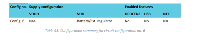
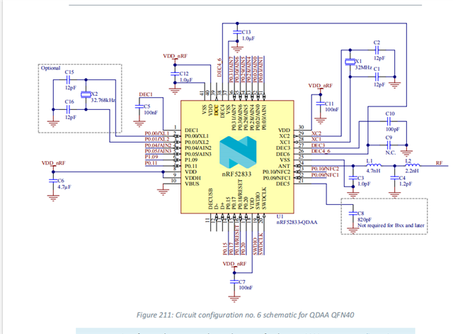
We are currently using the nRF52833-QDAA-R SoC for our R&D activities and have assembled the board based on Configuration 6. However, we encountered an issue during UART debugging:
-
When attempting to debug via FTDI using UART, no logs are observed.
-
Interestingly, when we solder the 10 µH and 15 µH inductors along with the DCC pin, the UART logs begin to function properly.
Please note the following:
-
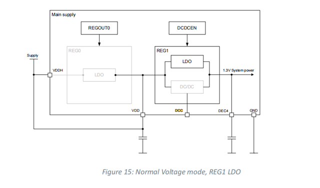
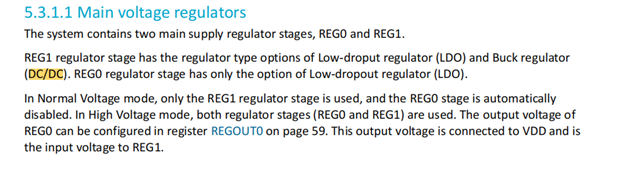
We are operating in normal voltage mode.
-
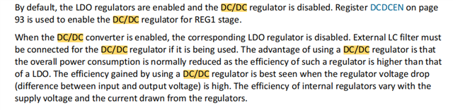
The DC/DC converter has not been enabled via register settings.
-
As per the datasheet, in this default state, the LDO regulator should be active, and the DC/DC converter disabled.
We kindly request your guidance on how the DCC pin and associated inductors might be affecting UART debugging, and whether we might be overlooking any critical design/configuration aspects.
Attached below are relevant datasheet snippets to support our query. Please review and advise.
Thanks & Regards,
Jhakan.M