Using PPK to measure the power of nRF54L15 DK made it broken

Hi

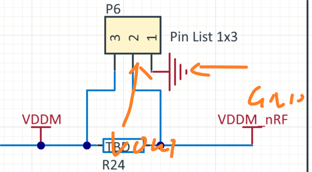
I have one nordic nRF54L15 DK using as peripheral, I want to know the power of it. Thus, I use PPK2 to be a 1.8 voltage source and connect VOUT to P6 pin 1 and GND to P6 pin 1 as the diagram shows:

At first it works well, but when I increase voltage to 3.7V, the DK is broken. I found that somehow P6 pin1 and P6 pin 2 are shorted.

I want to ask that whether this is a correct way to measure thre power. I have tried using current measurement but the power is somehow to samll, and it canot show the maximum current change when I tuning the TXP.  Whether P6 is only used to measure the current? By the way, how could I fix the development KIT.

Thank you so much!

Parents
  • The maximum voltage for the nRF54L15 is 3.6V so applying 3.7V is outside the maximum ratings and may damage the board.

    The VDD setting on the DK should be the same as applied to the nRF54L15, if there is a big difference then you may see issues with UART/Programming only or worst case, you may damage the Debugger on the board and thus break it.

    Attach the jumper agian and see if the board works, if so you should be good as long as you ensure to keep the voltages as stated above. If not then you may have broken the debugger and that would mean you'll need to get a new board.

Reply
  • The maximum voltage for the nRF54L15 is 3.6V so applying 3.7V is outside the maximum ratings and may damage the board.

    The VDD setting on the DK should be the same as applied to the nRF54L15, if there is a big difference then you may see issues with UART/Programming only or worst case, you may damage the Debugger on the board and thus break it.

    Attach the jumper agian and see if the board works, if so you should be good as long as you ensure to keep the voltages as stated above. If not then you may have broken the debugger and that would mean you'll need to get a new board.

Children
No Data
Related