Hello Nordic Team!
I'm experiencing unusual issues with GPIO pins on an nRF54L15 custom board. Specifically, P0.02 and P1.03 are not behaving as expected.
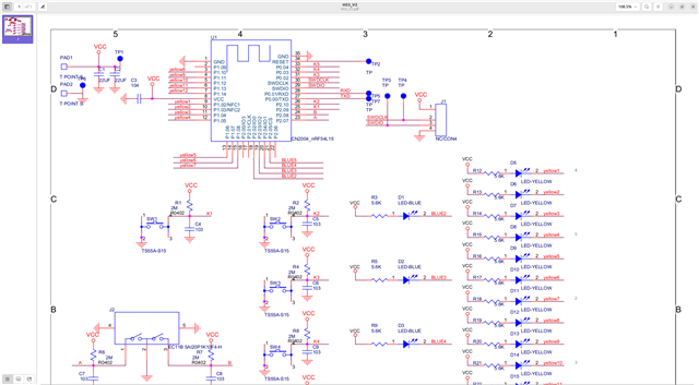
Button Issues (P0.02)
I have three buttons configured in my application:
- Button K1 on GPIO2_9
- Button K2 on GPIO2_10
- Button K3 on GPIO0_2
All GPIO pins are configured with `GPIO_ACTIVE_LOW | GPIO_PULL_UP`, meaning they should read as high (1) when not pressed and low (0) when pressed.
The problem with P0.02:
1. On startup, debug logs correctly show K3 as high (not pressed): `ButtonK3 initial state: 1`
2. Shortly after initialization, the button triggers a long press event without physical interaction: `K3 long press start (MultiButton)`
3. Continuous debug logs show the pin consistently reads as state 1, yet the button's pressed state persists
Here is the code:
Additional testing:
- I attempted to bind an interrupt event to P0.02 but failed, while P0.03 and P0.04 worked successfully
- Using a hardware testing tool, I found that P0.02 appears to be connected to GND when the board is powered on, but disconnects when power is removed
- This suggests some internal configuration is affecting the pin
LED Issue (P1.03)
I also can't properly control P1.03 for LED output, while P1.02 works fine. I have already set `CONFIG_NFCT_PINS_AS_GPIOS=y` in my configuration.
Configuration Details
SDK version: nRF Connect SDK v3.0.0
Build arguments: `-DFILE_SUFFIX="internal"`
My overlay file contains:
UART is functioning properly and I can see the debug output.
## Questions
1. Is P0.02 a special pin on nRF54L15 that might have default functions affecting its GPIO behavior?
2. Even though I've disabled hardware flow control for UART, could other internal functions be affecting this pin?
3. Are there specific configurations needed to use P0.02 and P1.03 reliably as GPIO pins?
4. Could there be a conflict with another peripheral that's claiming these pins?
Thank you for your assistance!
Best regards,
Xiongwei.wang