Battery level reading using ADC pin from nRF chip shows significant fluctuation

Hi everyone,

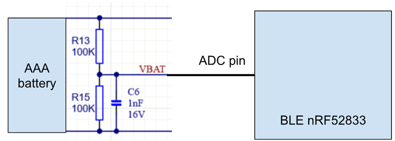
We're reading BAT level by reading data from ADC pin and the setup diagram is shown below. 
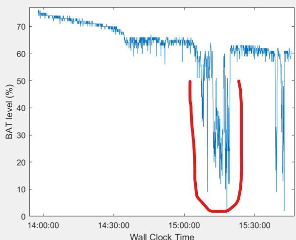
We tested our device at hospital, and we observed significant fluctuation highlighted in red regarding its BAT level. For example, it went from 65% to 20%, then jumped to 60% again. 
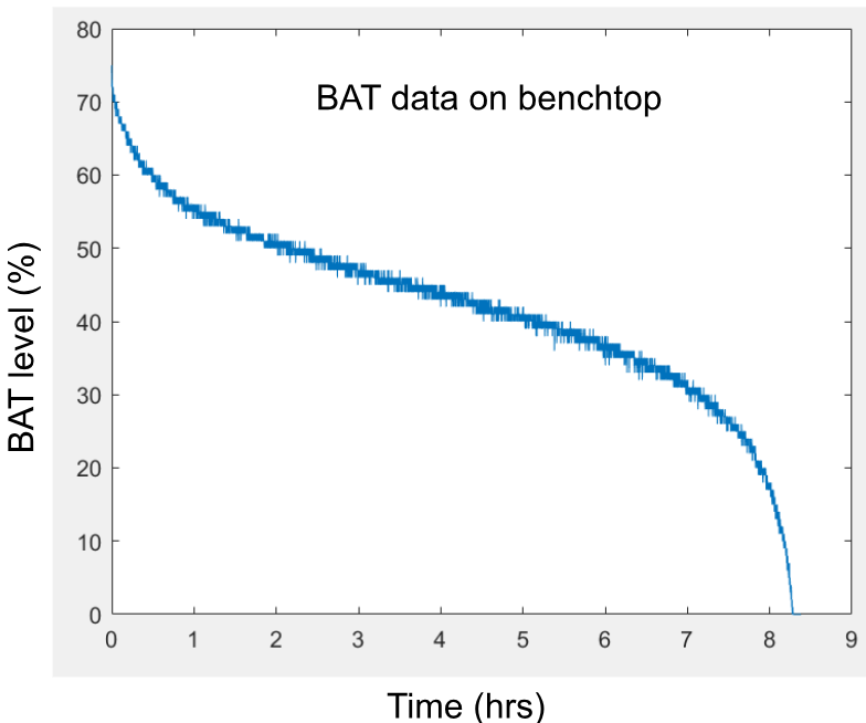
We then took the device and battery back to the office and tried to reproduce the issue on benchtop. However, we couldn't reproduce it. In contrast, the following is what we got, and it worked as expected.
Our hypothesis is that it could be due to the impedance mismatch between ADC input pin and the output of voltage divider. However, based on our calculation, the input impedance of the voltage divider is equivalent to R13//R15 (50kOhm) while the input impedance of ADC pin is more than 1MOhm. This would not cause the impedance mismatch. 

I greatly appreciate if anyone has any suggestions for this issue. Thanks.

  • Tai said:
    On the firmware side, a potential flaw is the application being kept up and waiting for transmission to complete instead of being put to sleep. It's worth checking if this is happening and avoid it.

    Hi Hieu . Just wanted to follow up on this. Could you elaborate it more?

    I mean avoid these kinds of approaches:

    ret_code = try_send_notification(...);
    while (ret_code == BUFFER_FULL_TRY_AGAIN) {
        ret_code = try_send_notification(...);
    }

    An example is when sd_ble_gatts_hvx() returns NRF_ERROR_RESOURCES.

    This kind of approach keeps the CPU up and running as long as the send attempt isn't successful, thus draw a lot of power. Instead, it is better to put the system to sleep and try again.

    I tried to look at your battery calculation. I am a little confused how the max physical voltage of 1.69V is associated with a reference voltage value of 805.

    Nonetheless, assuming that is a typo, and the physical max is 1.609V, I calculated this:

    V_physical voltage_var temp_voltage_percent
    1.65 825 105.63425
    1.60 800 98.592
    1.55 775 91.54975
    1.50 750 84.5075
    1.45 725 77.46525
    1.40 700 70.423
    1.35 675 63.38075
    1.30 650 56.3385
    1.25 625 49.29625
    1.20 600 42.254
    1.15 575 35.21175
    1.1 550 28.1695
    1.05 525 21.12725
    1 500 14.085
    0.95 475 7.04275

    Assuming the reading dip is due to an actual physical voltage dip due to consumption, the dip will be roughly from 1.35V to 1.00V.

    I am quite weak when it comes to hardware, so I don't know if such a dip is explainable by increased consumption. However, I think we can replicate the lossy environment in your bench test by intentionally worsen the condition, such as by putting metal plate on top of the antenna. You can try setting that up, confirm via sniffer or the Power Profiler that the connection is actually bad, and then monitor the battery calculation.

  • Your enthusiasm was recognized, Hieu ^^. Thanks for this!

Related